personal website of ryan r. curtin

Cultural influences [1] suggest that expertise at pinball could be a useful social goal. Developing this expertise is likely best accomplished via ownership of a pinball machine, and thus it was decided that it was a worthy goal to obtain a pinball machine. This page details the process of developing this expertise. Unfortunately, no social payoffs have yet been found, and thus it must be considered that the original premise was incorrect.
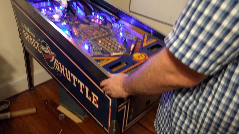
Unfortunately, time constraints meant that once this decision was made, a pinball machine needed to be purchased within hours. After spending a small amount of time searching for a machine [2], a Space Shuttle [3] was located and purchased. In retrospect, a good knowledge of pinball machines is even required to buy a good pinball machine. Nonetheless, the electronic expertise of those involved meant that something of a challenge for restoration was desired.
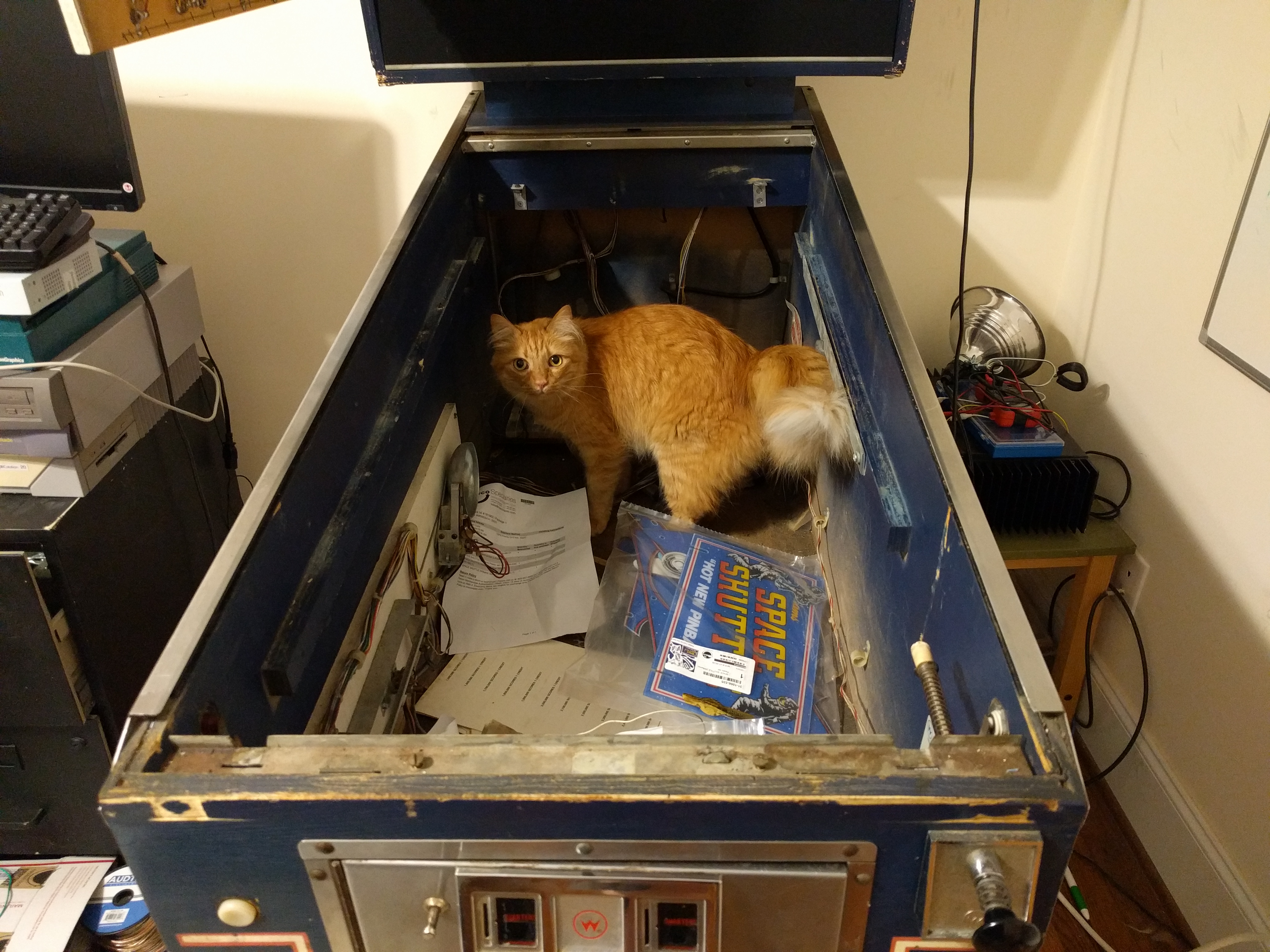
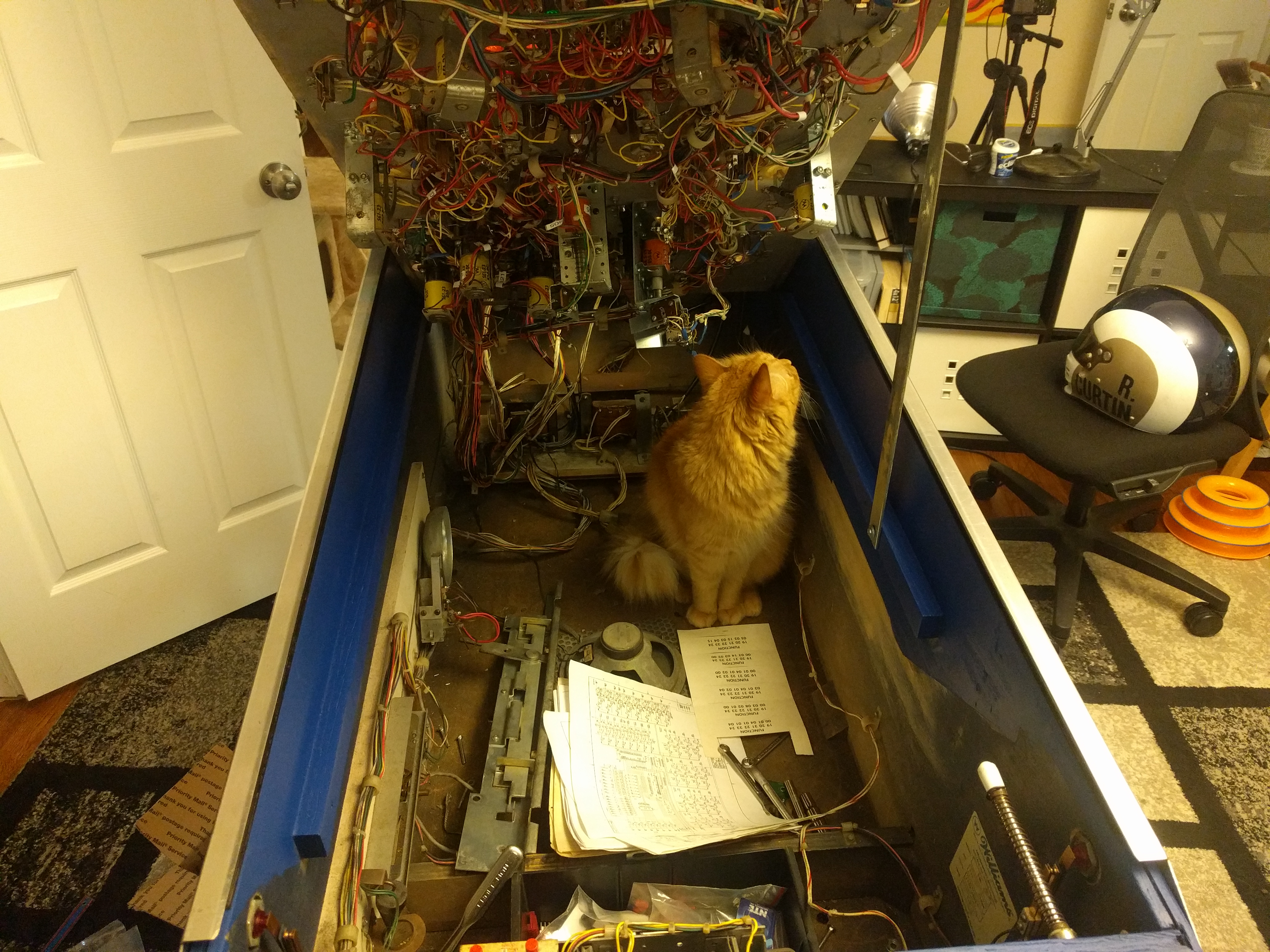
At first inspection, the Space Shuttle was in poor condition. See Figures 1 through 3. The machine also did not work, and at the time of purchase its only apparent utility was discovered by feline residents (see Figure 4.) Many of the lights in the machine were inoperable and the MPU board was clearly not booting up to start a game. In fact, once the MPU board was removed, a large burn mark was evident. The situation causing the burn was not reported by the previous owner, but it seems likely that open flame was involved.
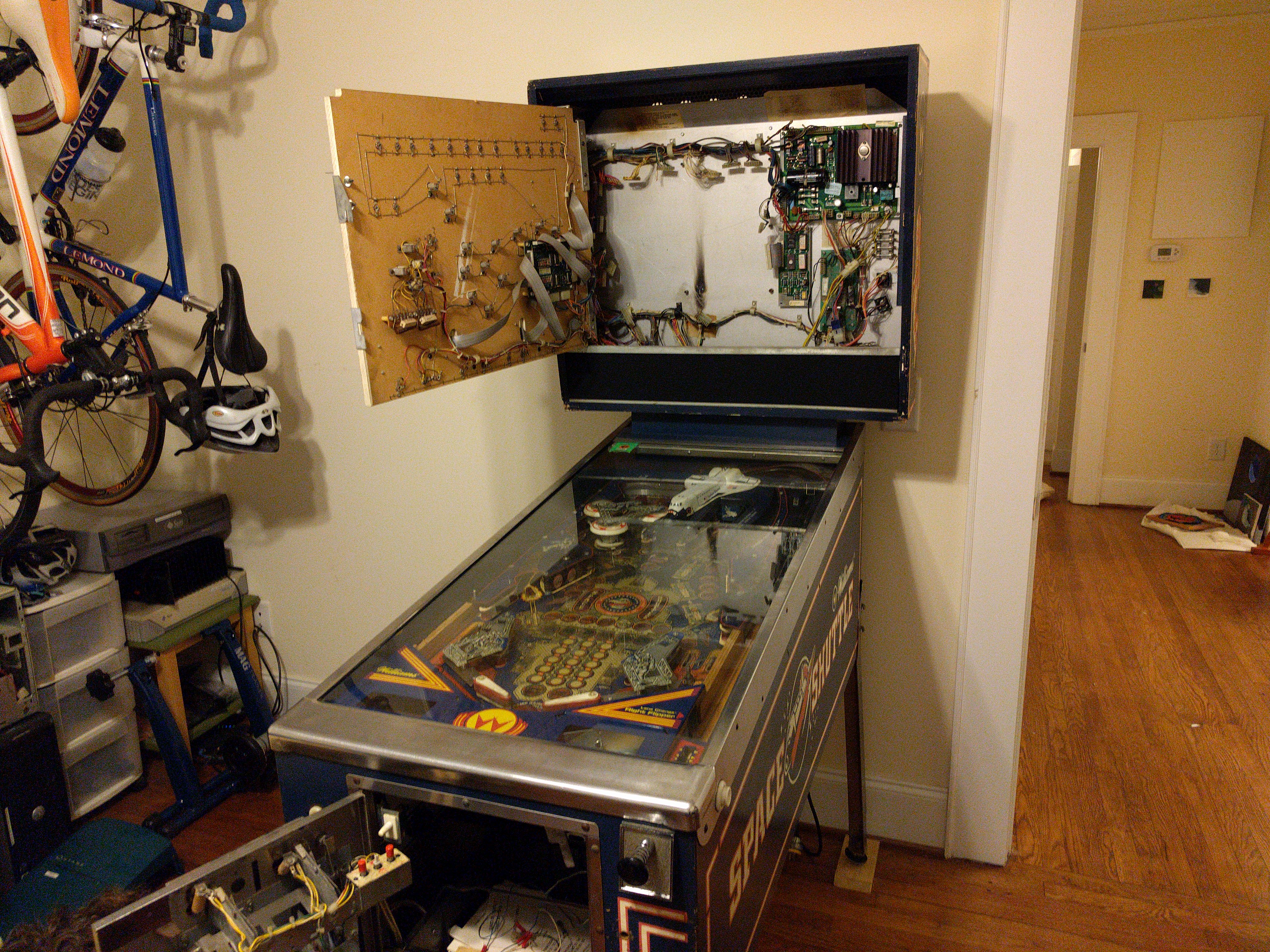
Figure 1. With the MPU board removed, a burn mark exists on the backing plate. |
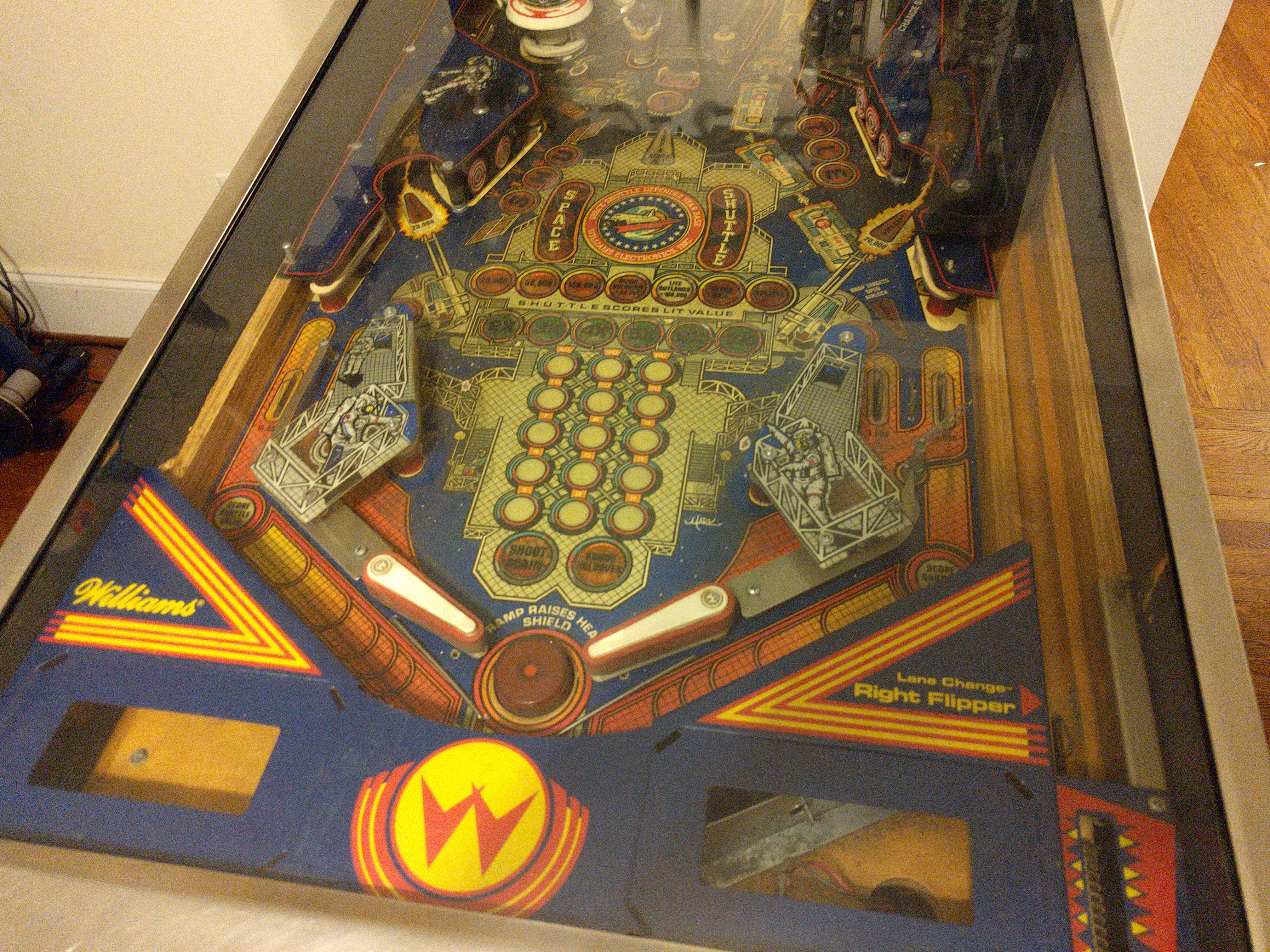
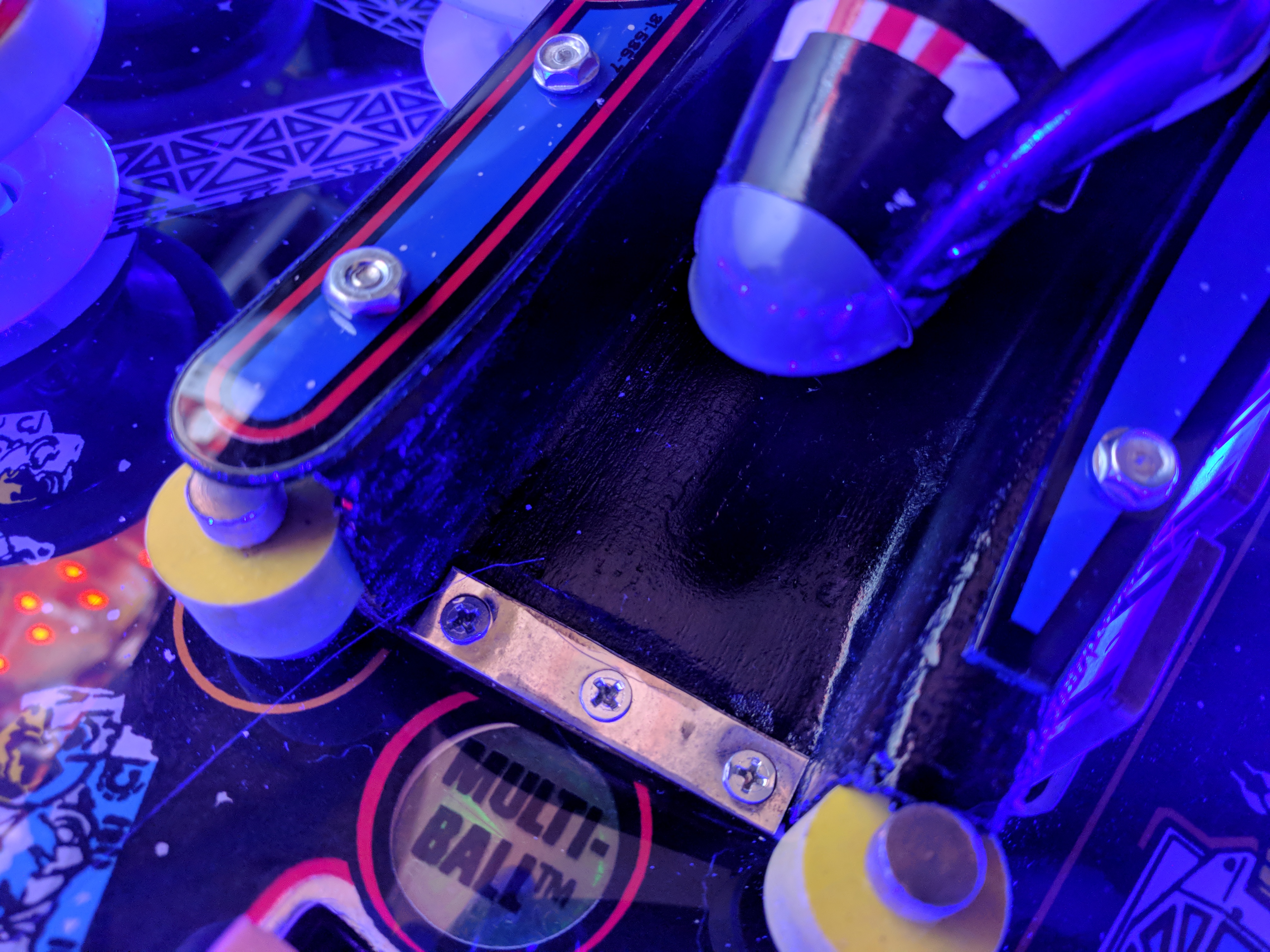
Figure 2. The playfield condition was very poor. |
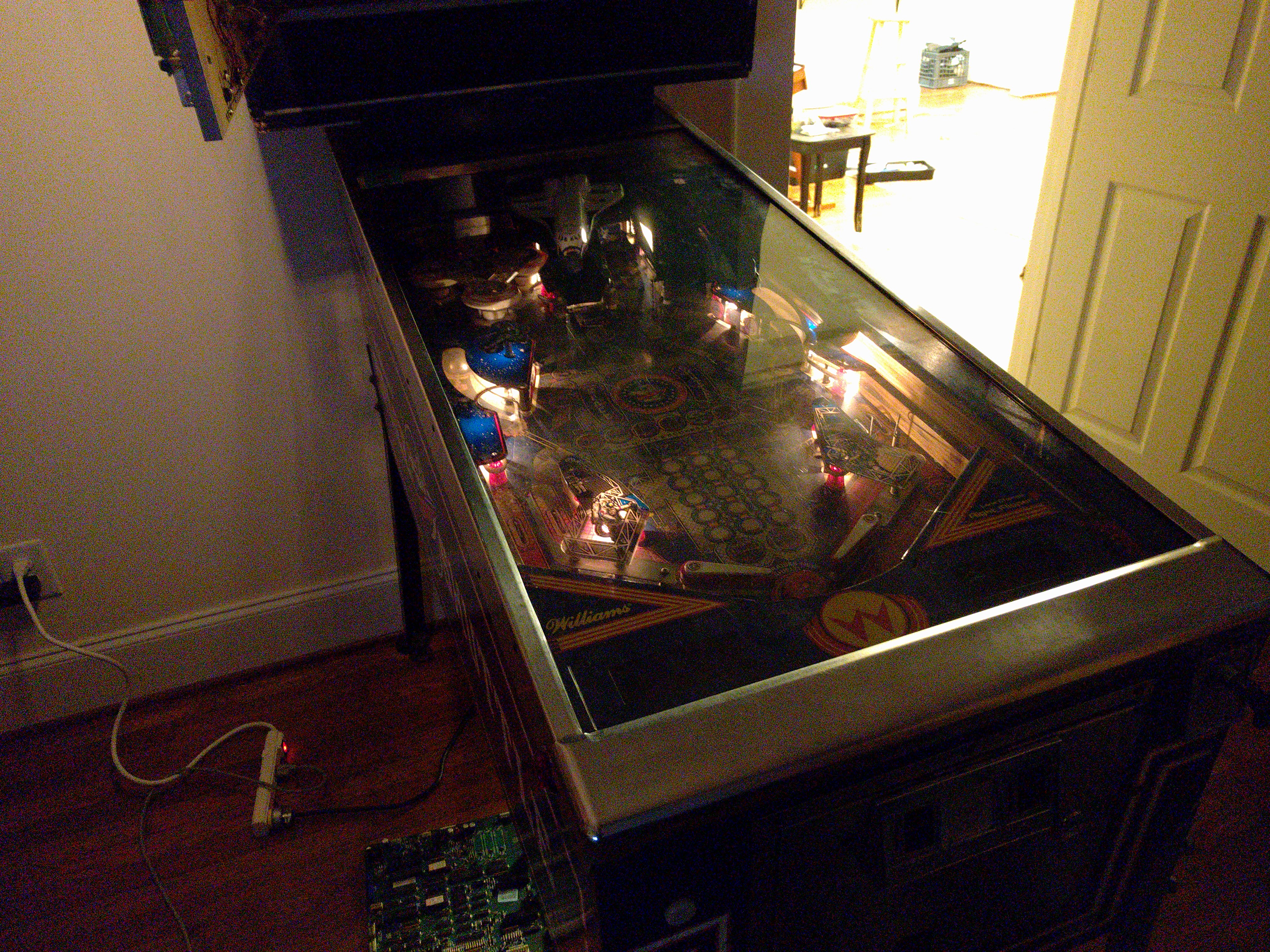
Figure 3. Most lights were inoperable. |

Figure 4. The purchase can be justified via this usage. |
Inspection revealed that the burn mark was right behind where the power supply connected to the MPU board (see Figure 5). Given that the +12V and -12V pins are right next to each other [4] (pdf), the cause of the fire was most likely that someone incorrectly plugged in the power supply, and nearly immediately lit the machine on fire. Figure 6 shows that many solder joints on the board were also in very poor condition or broken completely. This type of phenomenon was typically found near the transistors that power the various solenoids on the playfield. Further, the battery on the MPU board had leaked and caused corrosion everywhere, complicating the task of restoration.
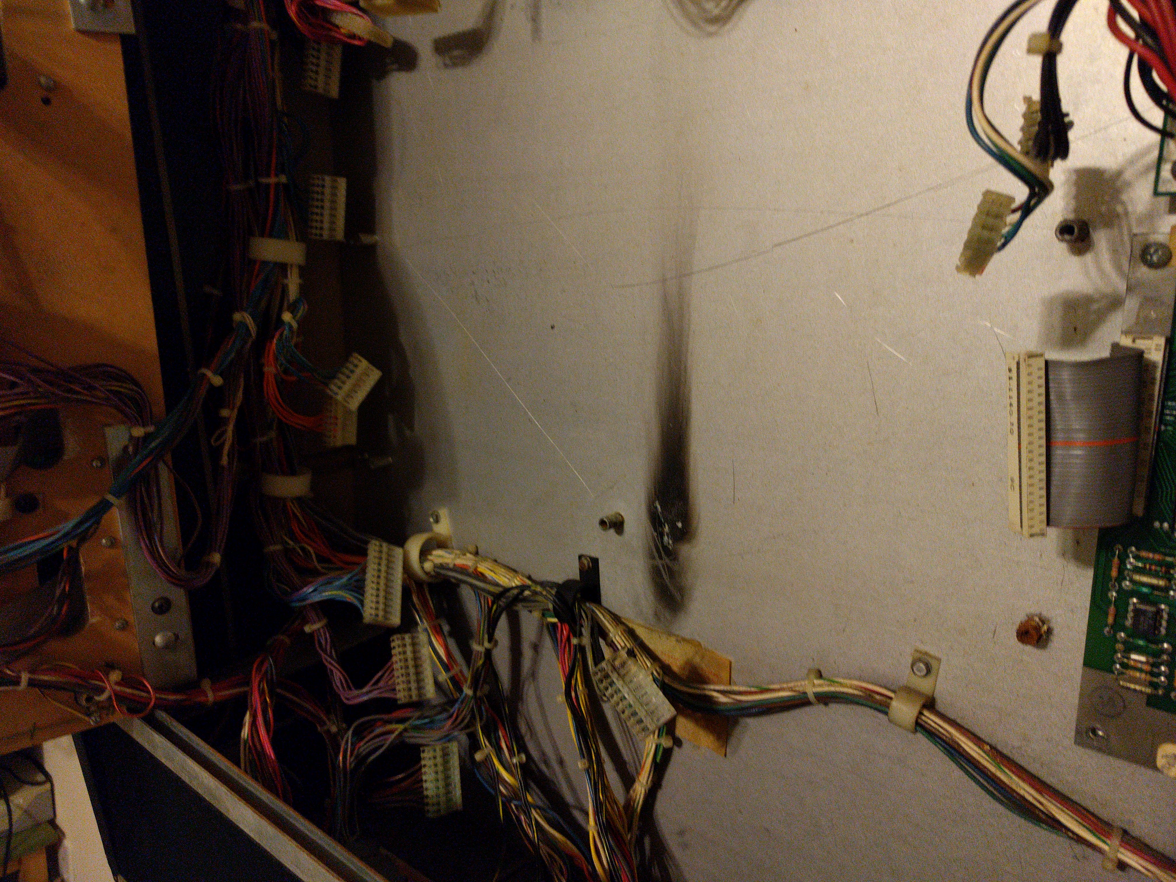
Figure 5. A closer look at the burn mark. |
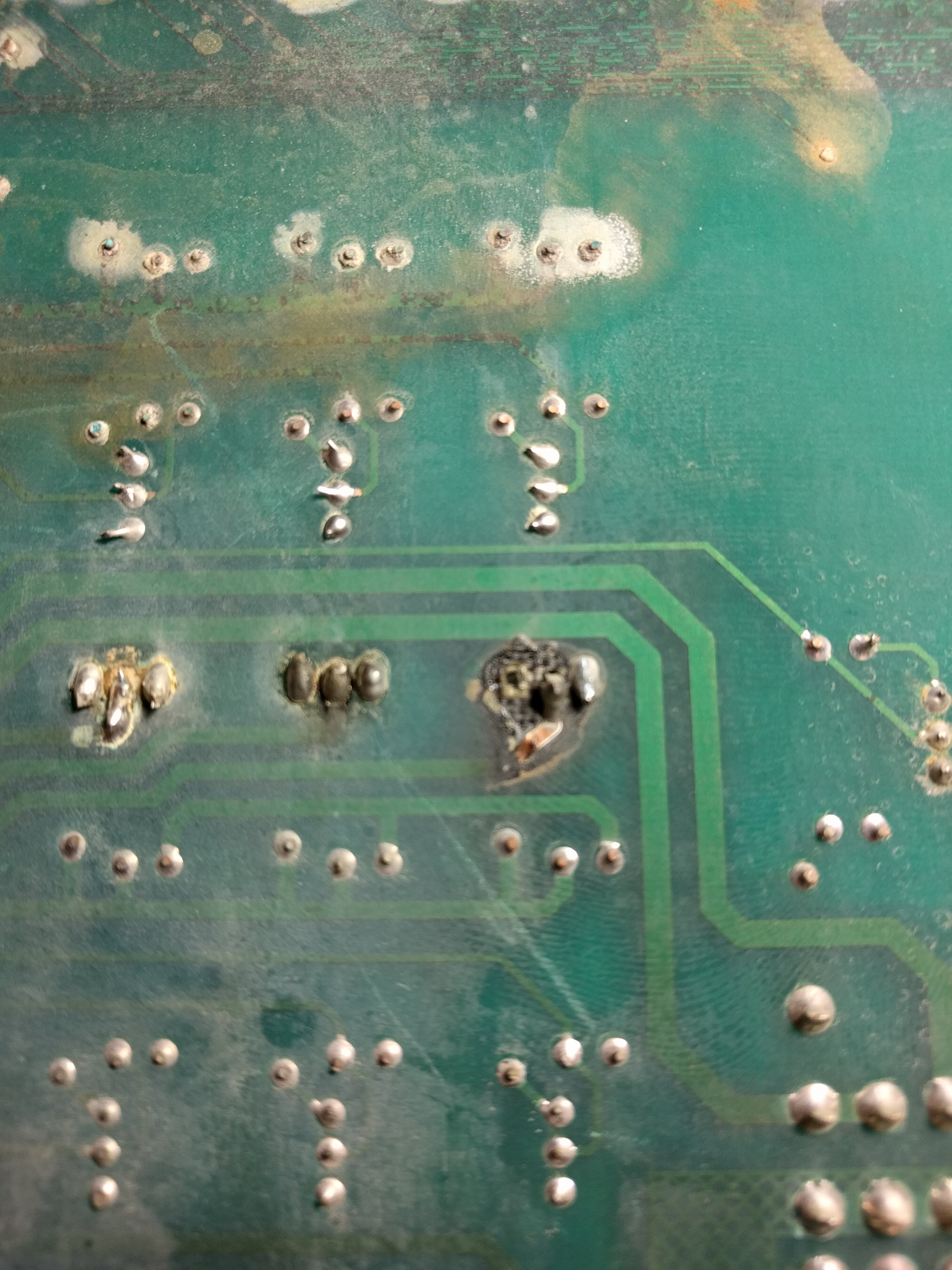
Figure 6. Many solder joints on the board were in very poor condition. |
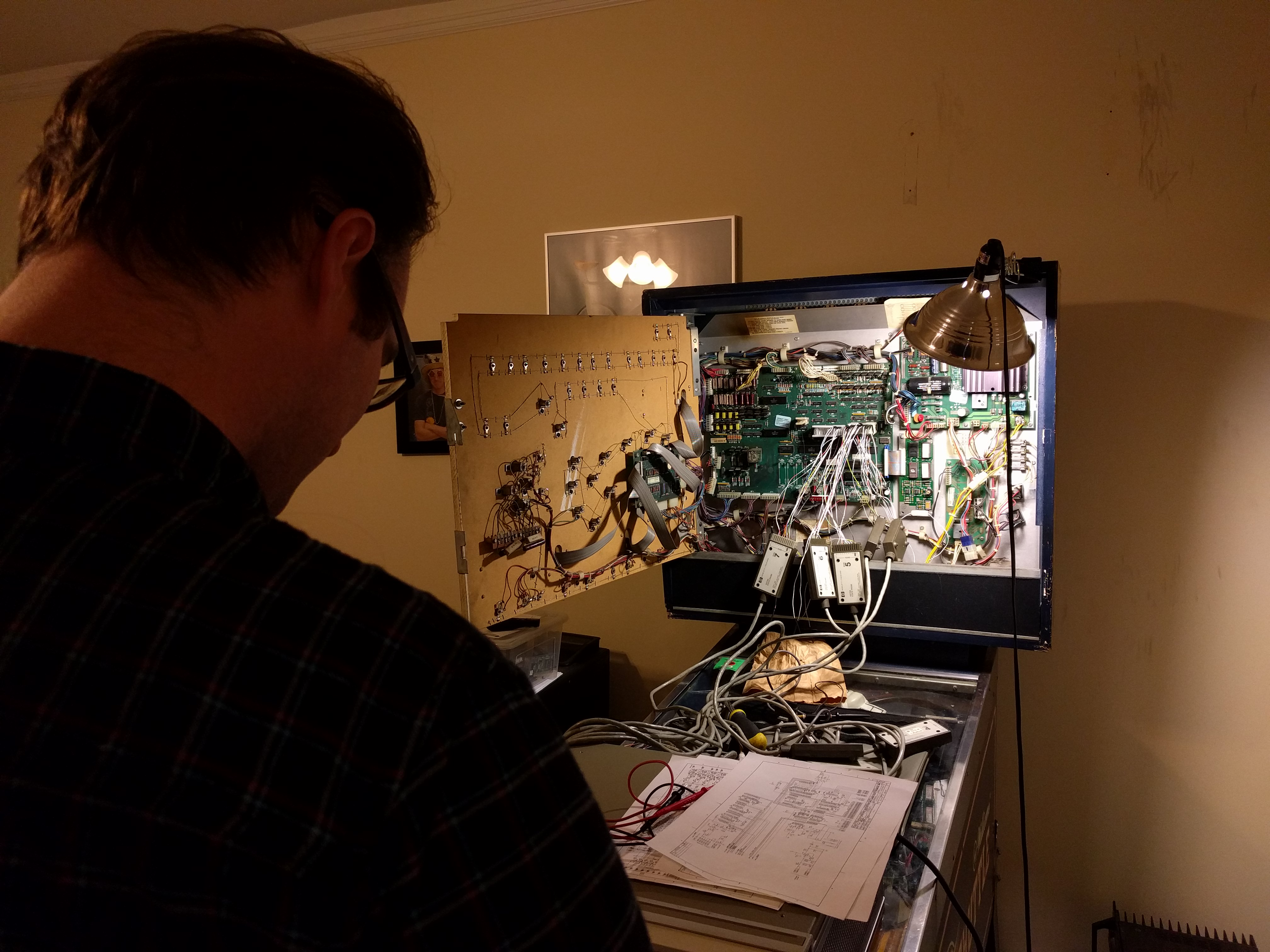
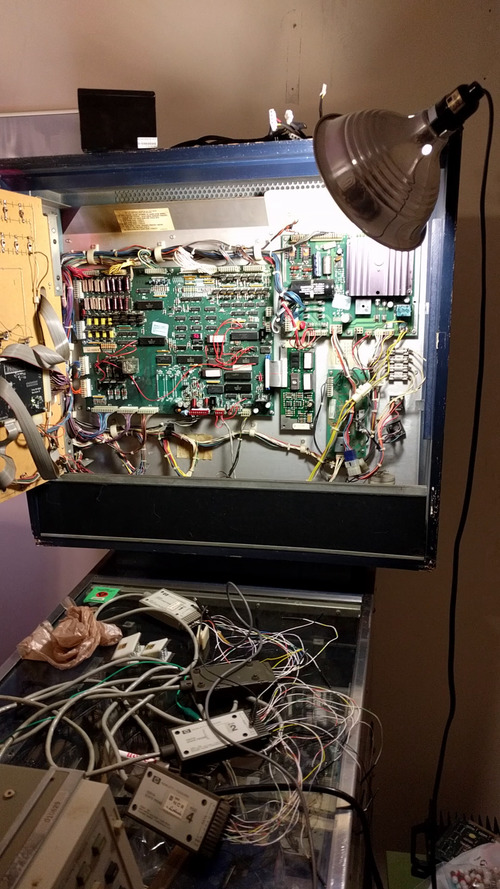
At this point it became clear that the route to social acceptance via expertise at playing pinball was not going to be a quick option. This was further compounded by the fact that the engineers involved in the operation also decided that purchasing a perfectly good new MPU board [5] was not the desired option, and instead a period-appropriate logic analyzer that was obtained from a junkyard [6] would be used to debug all issues with the MPU board and restore it to working order. Figure 7 shows a typical setup.
The Space Shuttle is a Williams System 9 pinball machine [7]. The System 9 board was used for a handful of different games in roughly the mid-1980s. The system actually contains two MPUs, both containing Motorola 6800-series processors [8]. One of these MPUs controls the game state, and another is used for sound. See Figure 8 for a general schematic of the main game control MPU.
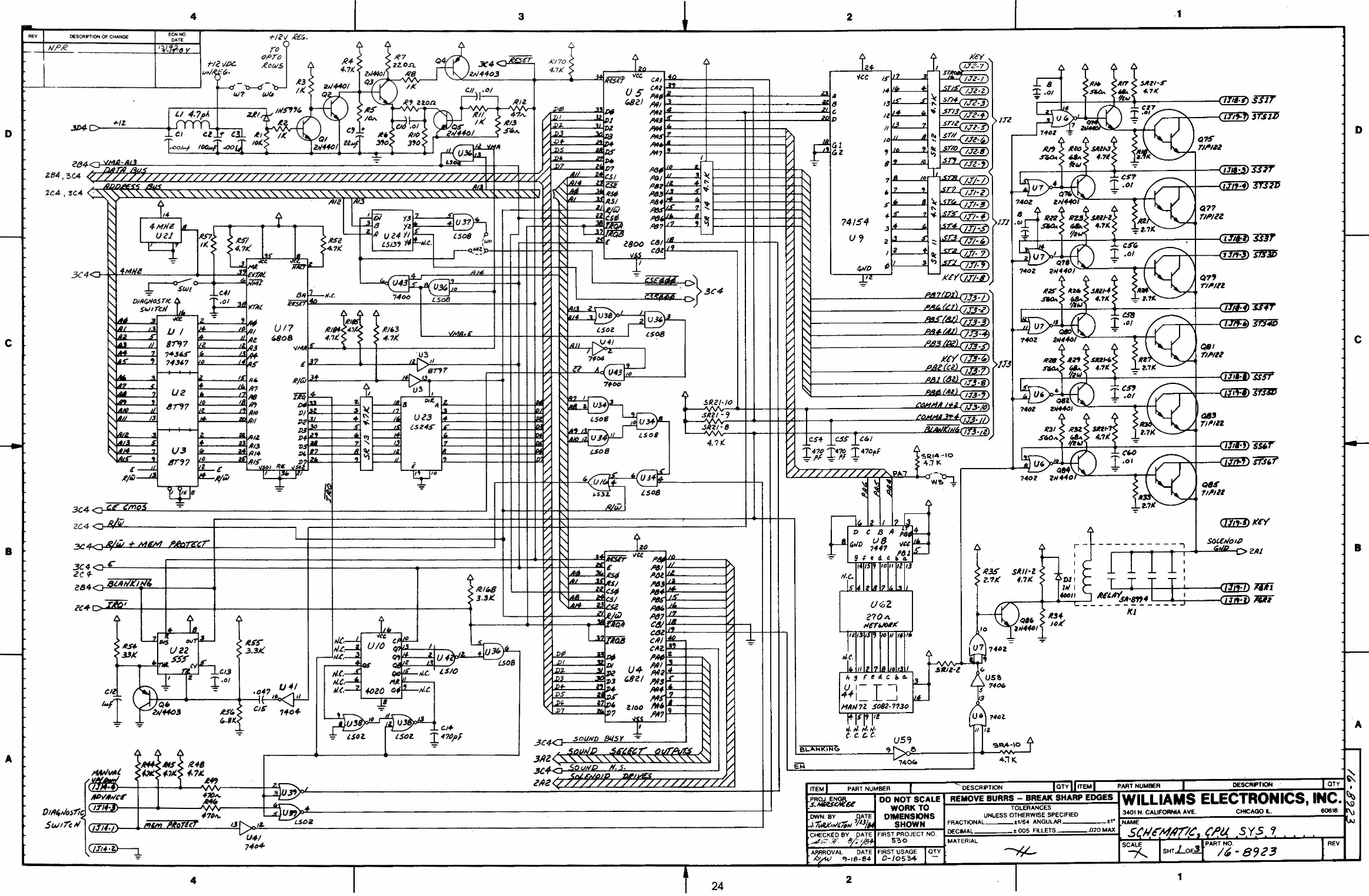
The general setup of the machine is that the processor interacts with the physical machine via the use of MC6821 PIOs [9] (pdf). These PIOs are used for input, collecting the state of each of the switches on the playfield, and also for output, setting whether solenoids or lights are enabled or disabled. The main processor interacts with the sound processor also via a PIO, which will set an interrupt for the sound processor that causes it to play sound.
Needless to say, for this setup to work, all of the wires must be connected. It was observed during the restoration process---which took many weekends---that the address bus was no longer connected (due to corrosion) to the main processor, and some bits on the data bus were also disconnected from many PIOs. In addition, the clock signal was not connected to many devices on the board, and the reset circuit (pictured in the top left of Figure 8 and used to initialize the machine correctly on power-on) had numerous disconnections. In fact, during the restoration process it was decided that the original design was lacking, and it was modified. After this modification, the reset signal was no longer an issue that was encountered during the restoration process.
Overall, during the debugging process, several main sources of problems were identified:
Every destroyed trace was simply replaced with a bodge wire. A random number generator was used to decide whether to place the bodge wire on the front or the back of the board, and sometimes bodge wires were connected directly to chip leads, obviating the sockets that were used in the original construction to allow fast replacement of chips. The most impressive bodge wire architecture is shown in Figure 9.

Eventually, after many hours of surely pointless labor and bodging, the board entered a state where it could start and play a game. Video 2 documents this thrilling development.
The other part of the MPU board was the sound and speech processor. In fact, the Space Shuttle uses an off-board speech processor, with the same TI chip used in the Speak & Spell toy [10]. Video 3 shows the out-of-the-box functionality of the speech board. The only debugging necessary was the connection from the main processor board to the speech board. It is currently believed that the speech board immediately worked as a result of its not having ever been on fire.
In the end, the MPU board was restored to a precarious but working state. Final images of the restored board can be seen in Figures 10 and 11.

Figure 10. Top of fully restored board. Roughly 10 chips had to be replaced and numerous bodge wires were necessary. |
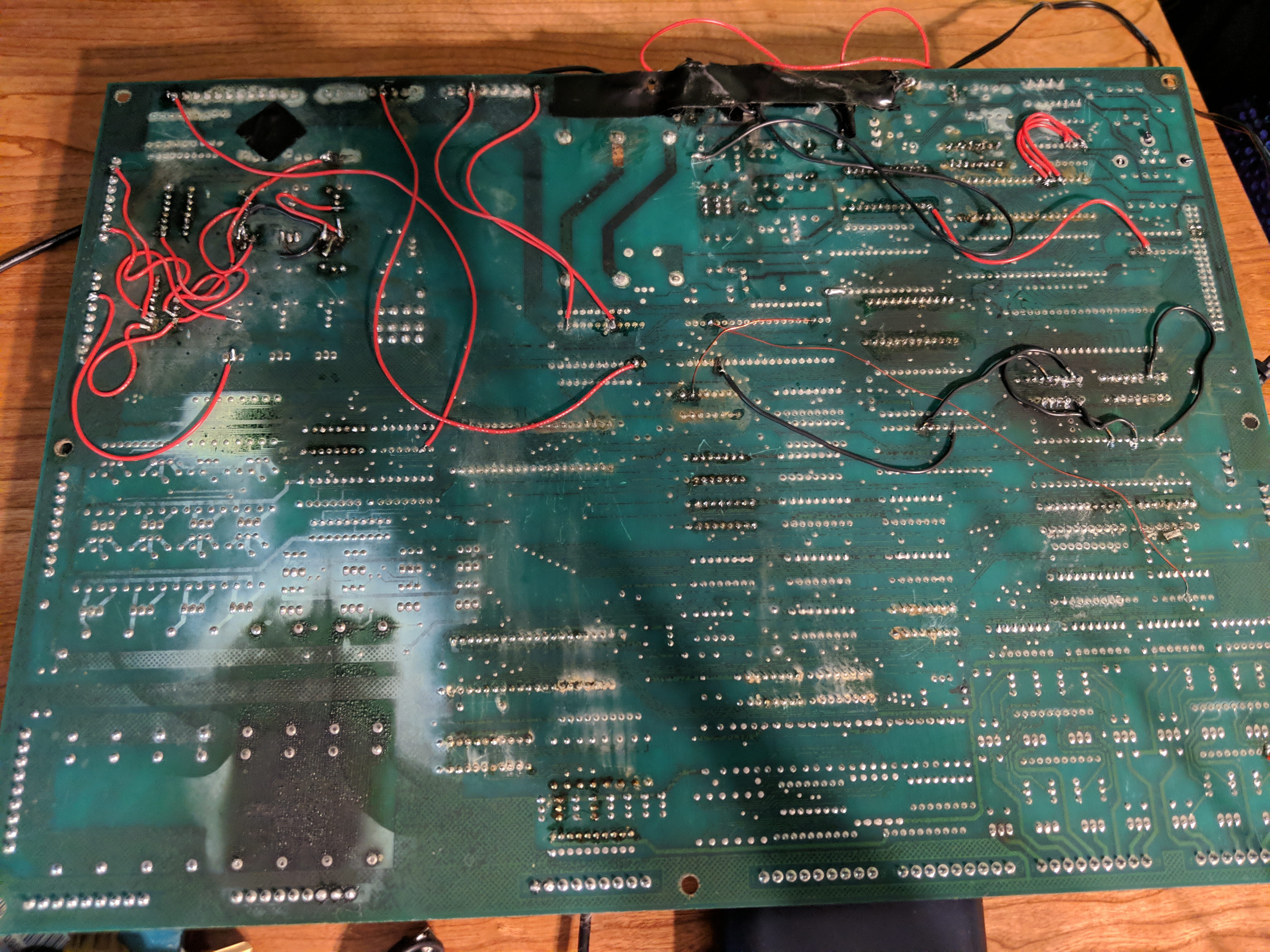
Figure 11. Bottom of fully restored board. The area near the original burn is covered in electrical tape to prevent exposed circuit traces from shorting to each other or to the backplane. |
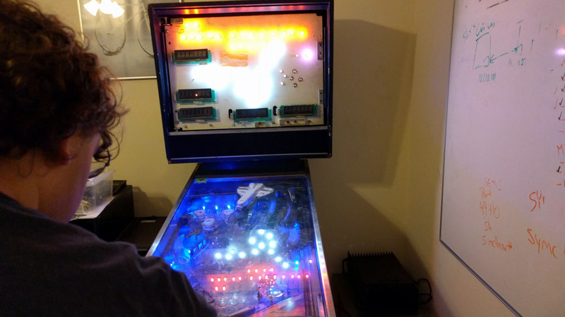
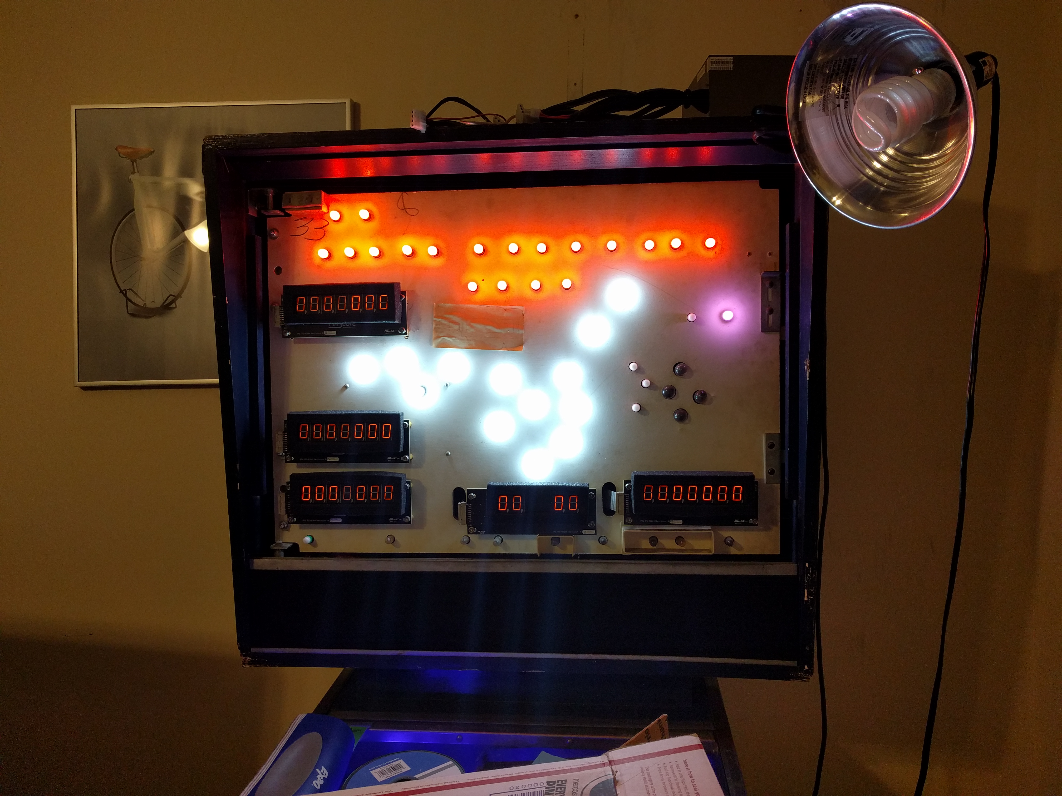
The original condition of the playfield lights in Figure 3 was clearly unacceptable, if the Space Shuttle was intended to be used for social gain. Therefore, an LED light kit [11] was purchased and installed. In addition, a PinScore unit [12] was obtained to replace the failing numeric displays on the backbox. The superior results can be seen in Figure 12, as well as in other videos and figures throughout.
Once the MPU restoration was complete (see Section III), it was immediately decided (contrary to the original project goals) that the purpose of the pinball machine was not to have fun playing it, and thus disassembly of the playfield for complete restoration began. Removing the playfield had an unexpected impact on the feline residents of the house in which the Space Shuttle was stored; see Figure 13.
Disassembly of the machine revealed further the awful condition in which the playfield was; see Figure 14 and 15. During disassembly, an unusual moment of forward thinking resulted in collecting pictures of the entire bottom side of the playfield [13], shown in Figure 16.

Figure 14. Note the damaged playfield surface under the S and A lanes. |

Figure 15. Fully disassembled playfield mounted on rotisserie. |
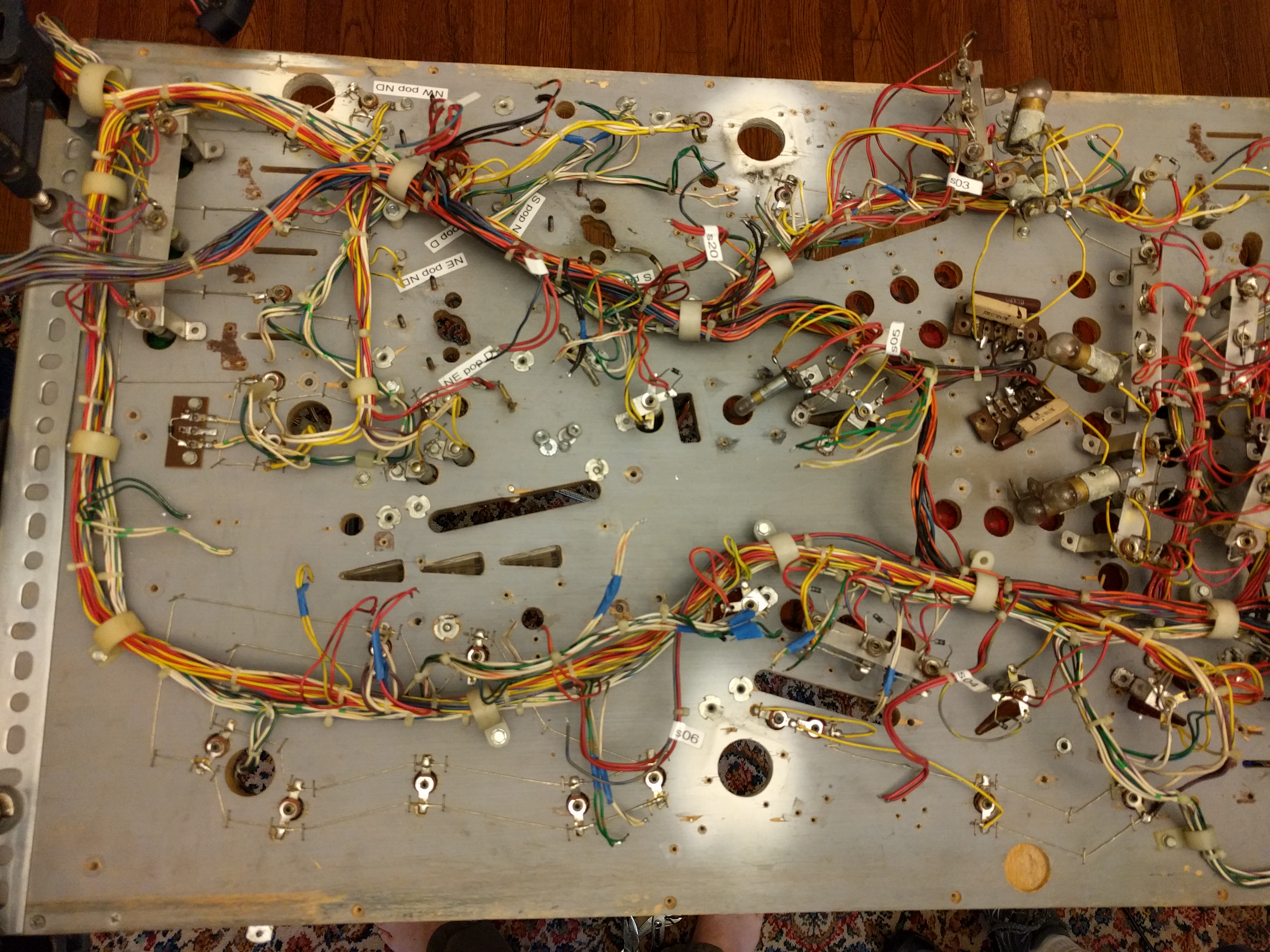
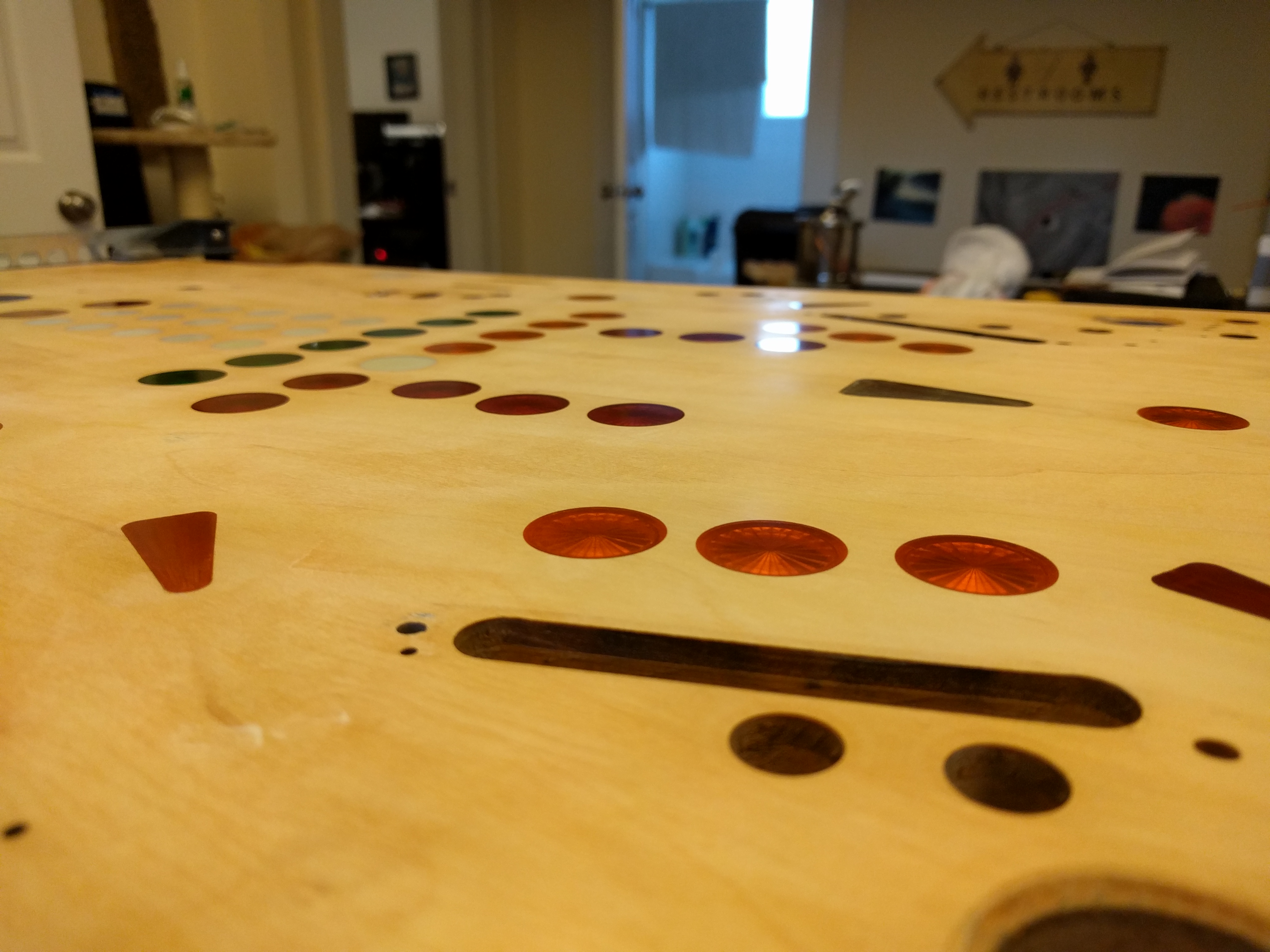
In the only example during the restoration of following someone else's advice, the engineers involved built a rotisserie according to directions found online [14] in order to hold the playfield while sanding it down to apply an overlay [15]. This rotisserie was the quickest success of any part of the entire project. Along with an orbital sander, the playfield was sanded up to 400 grit (see Figure 16), and each of the inserts was wet-sanded up to 2000 grit (see Figure 17). Figure 18 shows the reflectivity of the highly-sanded inserts and playfield.

Figure 16. Sanded playfield at 400 grit. |
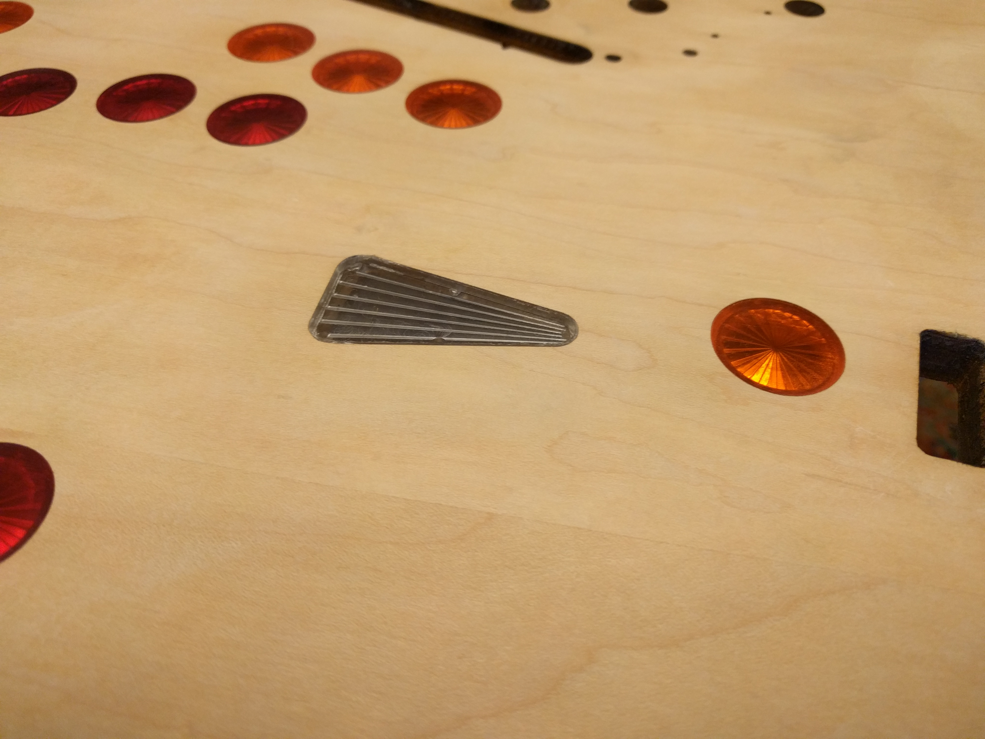
Figure 17. Sanded inserts at 2000 grit. |
Once sanded, the playfield overlay was then installed following the directions of the provider. See Figures 19 and 20. The installation process only took about 15 minutes---such quick progress in this process was quite rare. However, unfortunately, the alignment was not perfect, as can be seen in Figure 21.
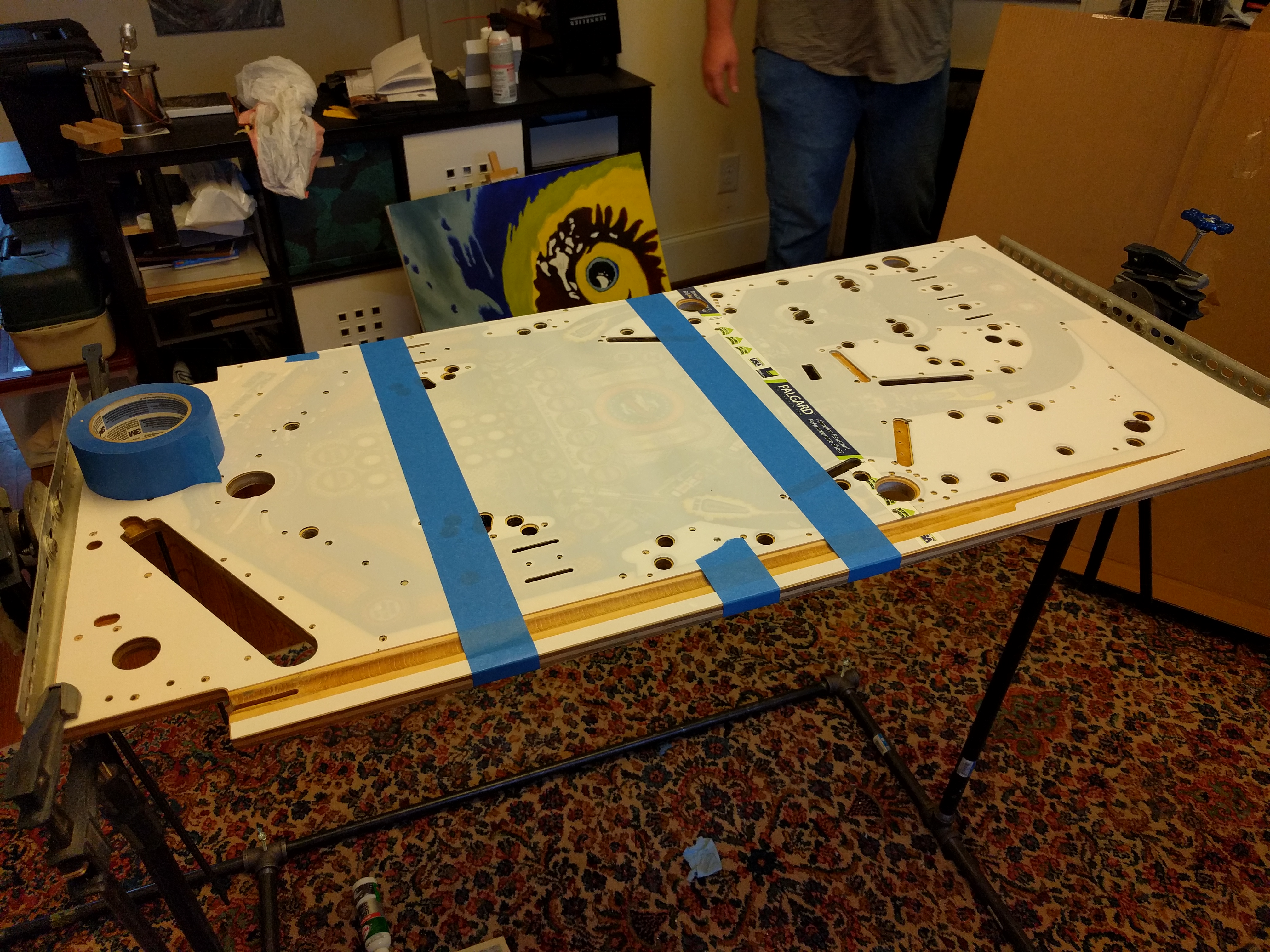
Figure 19. First, the overlay is affixed to the playfield in the right alignment via tape, with the adhesive on the overlay unexposed. Then, the adhesive is uncovered on each side to install the overlay, and the tape is removed. |
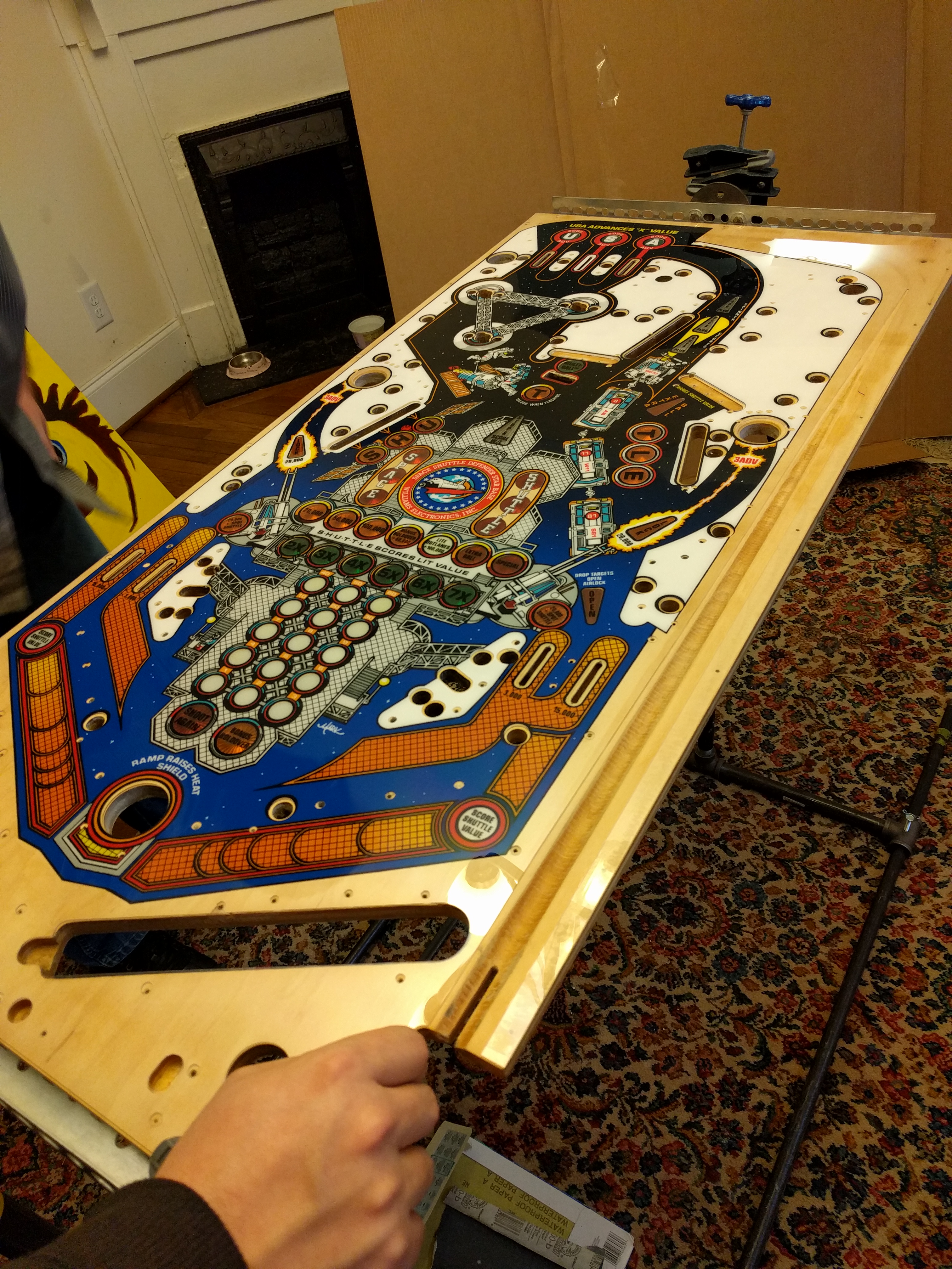
Figure 20. The installed overlay has a thick acrylic layer, reducing the potential for damage like that pictured in Figure 14. |
The reassembly process for the playfield was rather tedious and required a
lot of manual labor. In fact, by the time reassembly happened, the engineers
involved had forgotten that they had collected pictures of the original
reassembly, and thus reassembled it halfway before realizing that they had this
documentation. Therefore, partial re-disassembly was required.
V. Cabinet restoration
After restoring the MPU board and the playfield, the next thing that was obviously incorrect and also needed to be restored was the cabinet itself. Disassembly was fast, and the poor condition of the box can be seen in Figures 22 and 23.
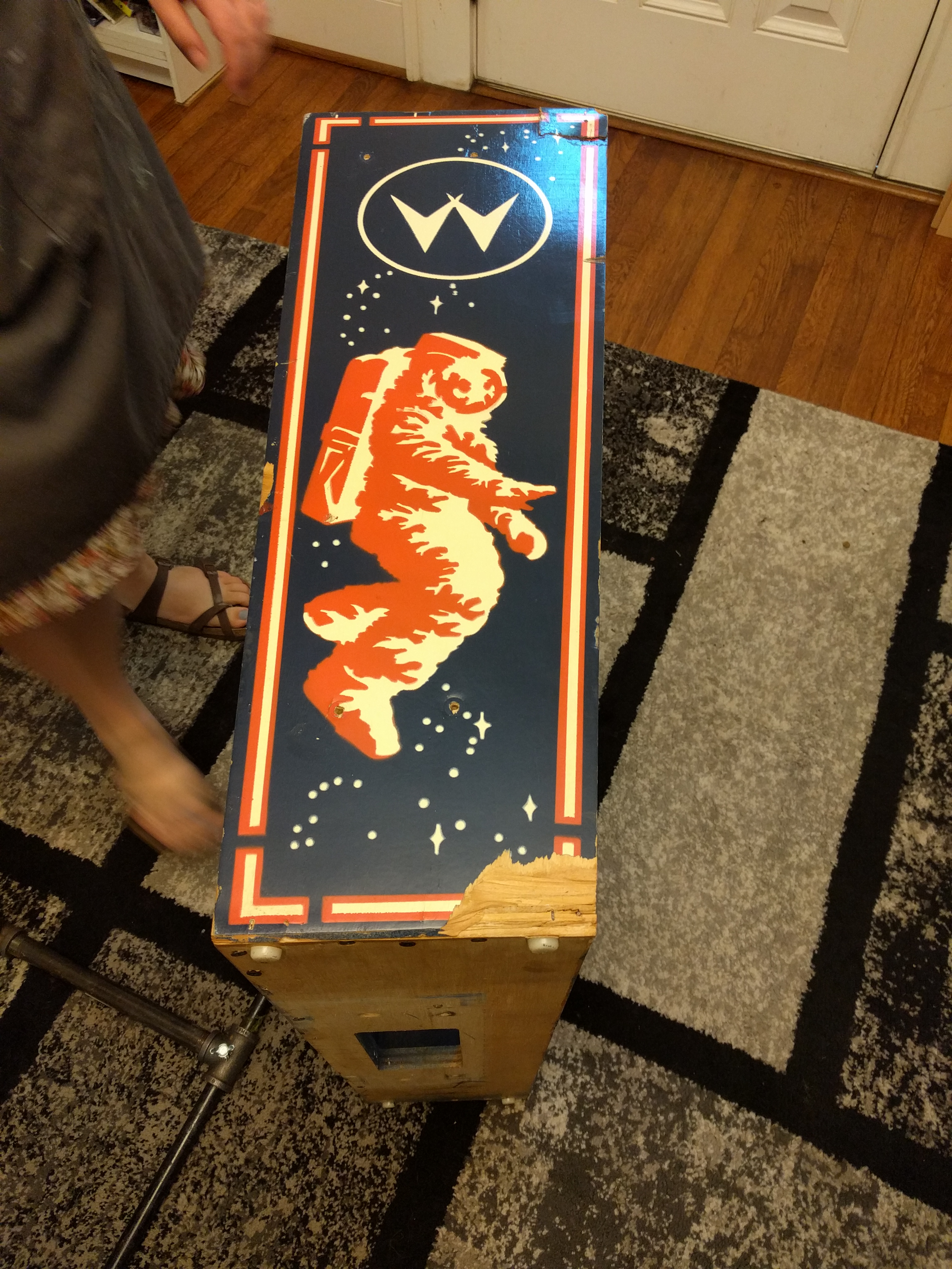
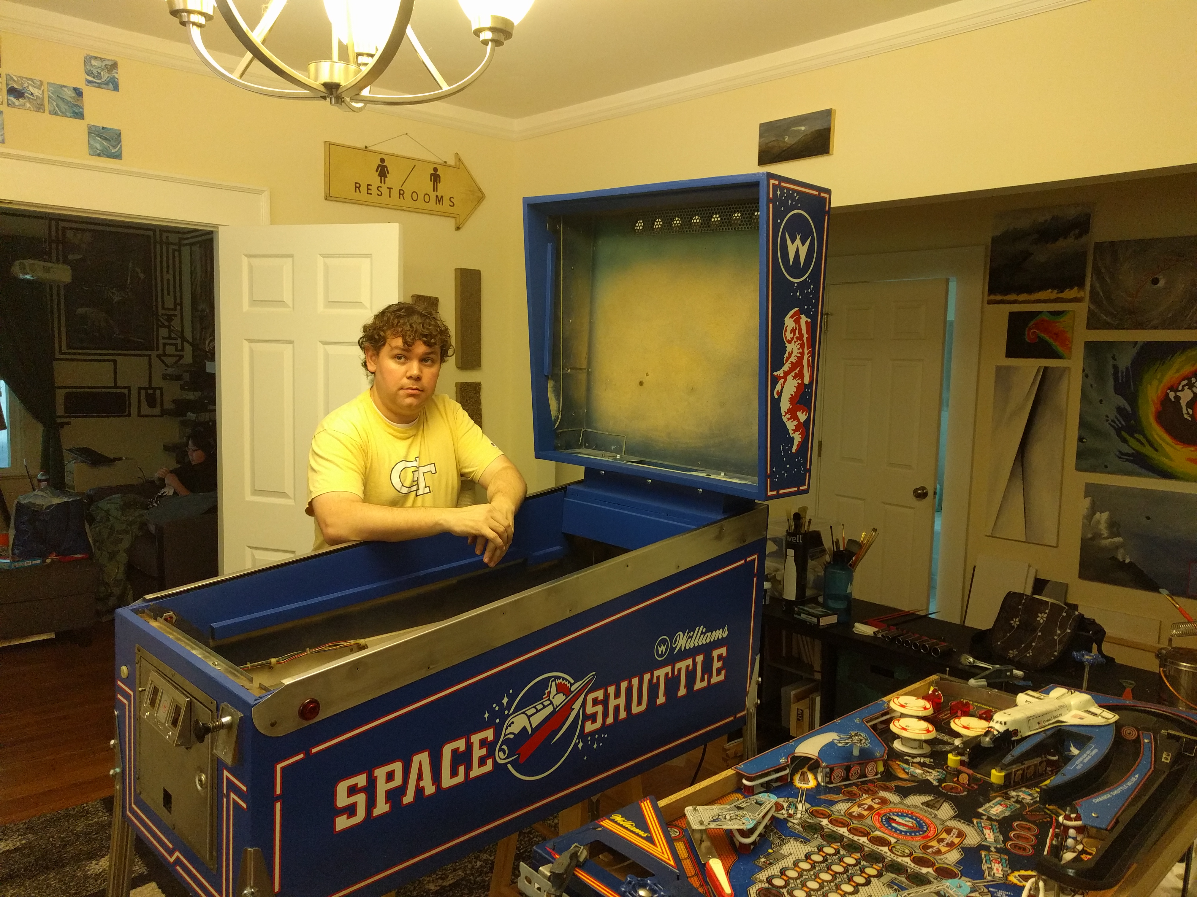
Figure 22. The backbox had severe and extensive damage. |
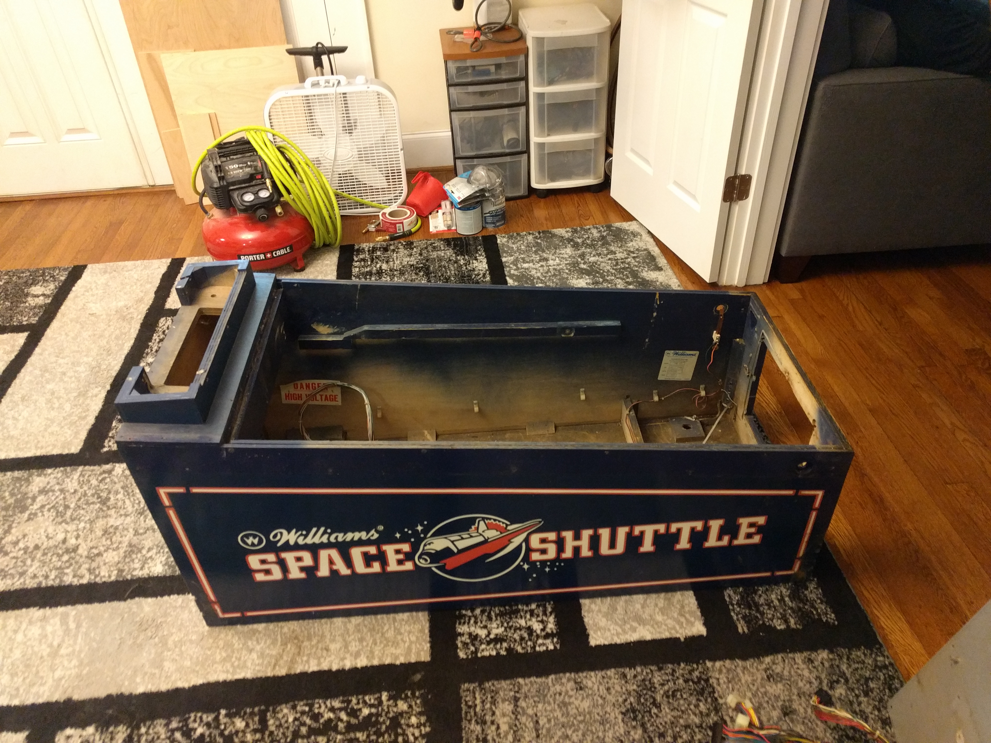
Figure 23. The rest of the cabinet was in better shape, but still had cosmetic imperfections and was rather faded. |
At this point, with the box entirely disassembled, it was sanded and wood filler was applied where necessary. Figures 24 and 25 show the sanded results. Note the lack of respiration in Figure 24. It is not clear if the engineers involved have learned the utility of respirators after this experience.

Figure 24. Sanding the backbox. |
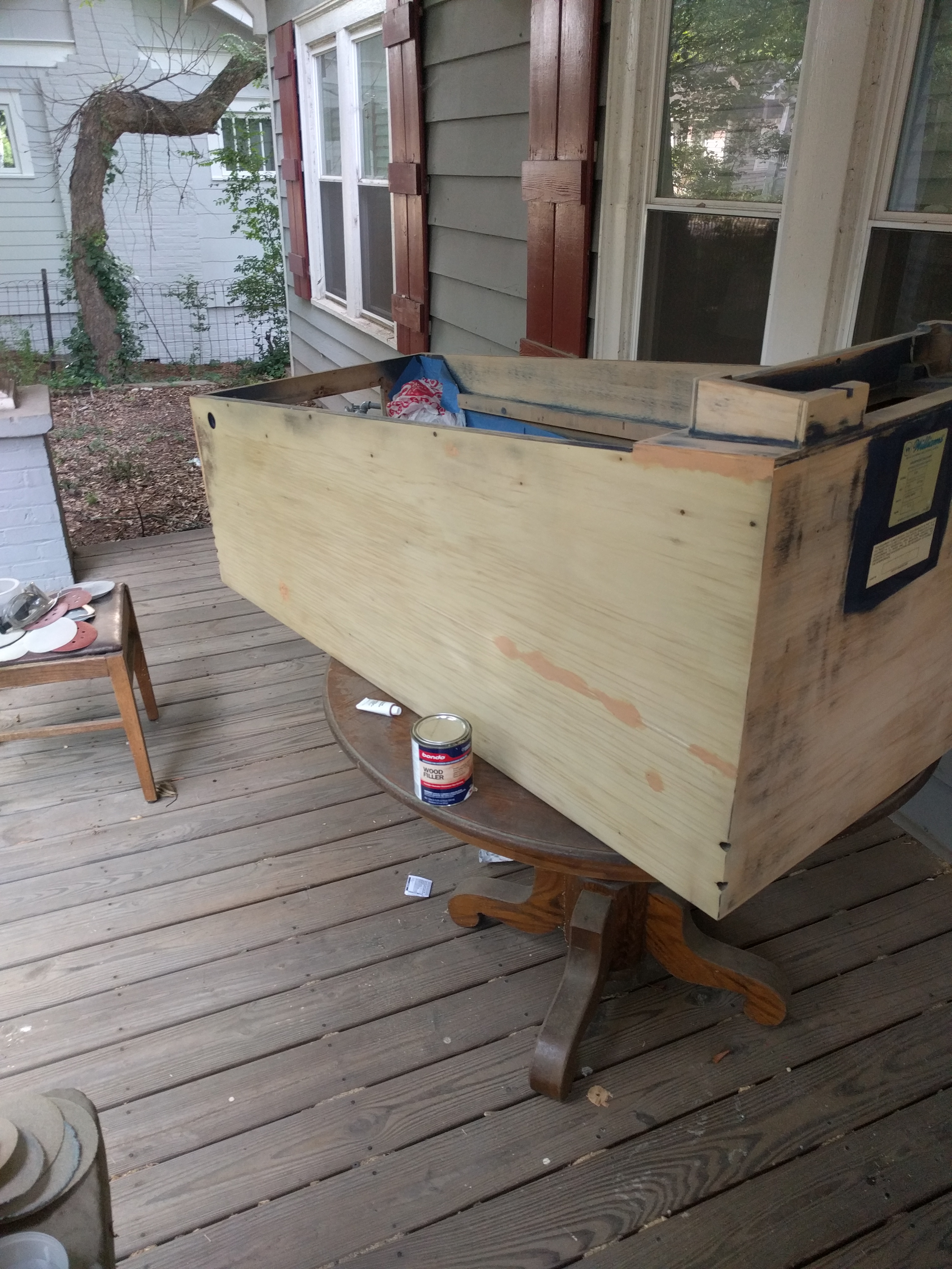
Figure 25. Fully sanded cabinet, ready for paint. Wood filler is visible (darker color). |
After sanding, a paint booth on the porch was hastily assembled. Several coats of blue would be applied, and then stencils [16] would be applied, first for red and then for white. The paint was applied via a pressurized paint sprayer. During this process, it was discovered that respirators are essential for this process, as atomized latex paint will quickly travel through one's digestive tract without being processed. The engineer involved with the painting commented that he was happy that red was not the first color. Pictures of this painting process are shown in Figures 26 through 37.
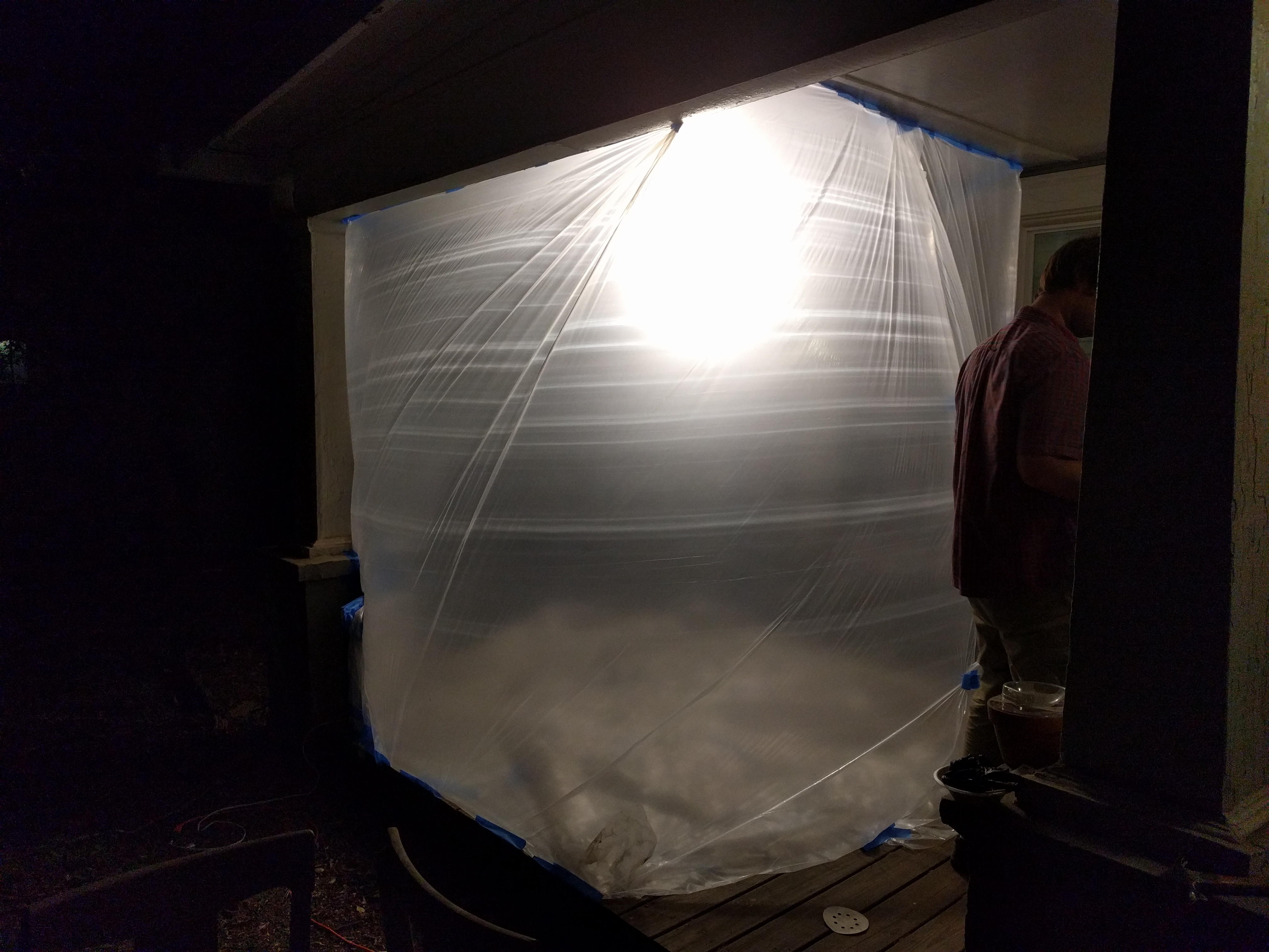
Figure 26. Paint booth assembled on porch, lit with appropriately named painter's lamp. |
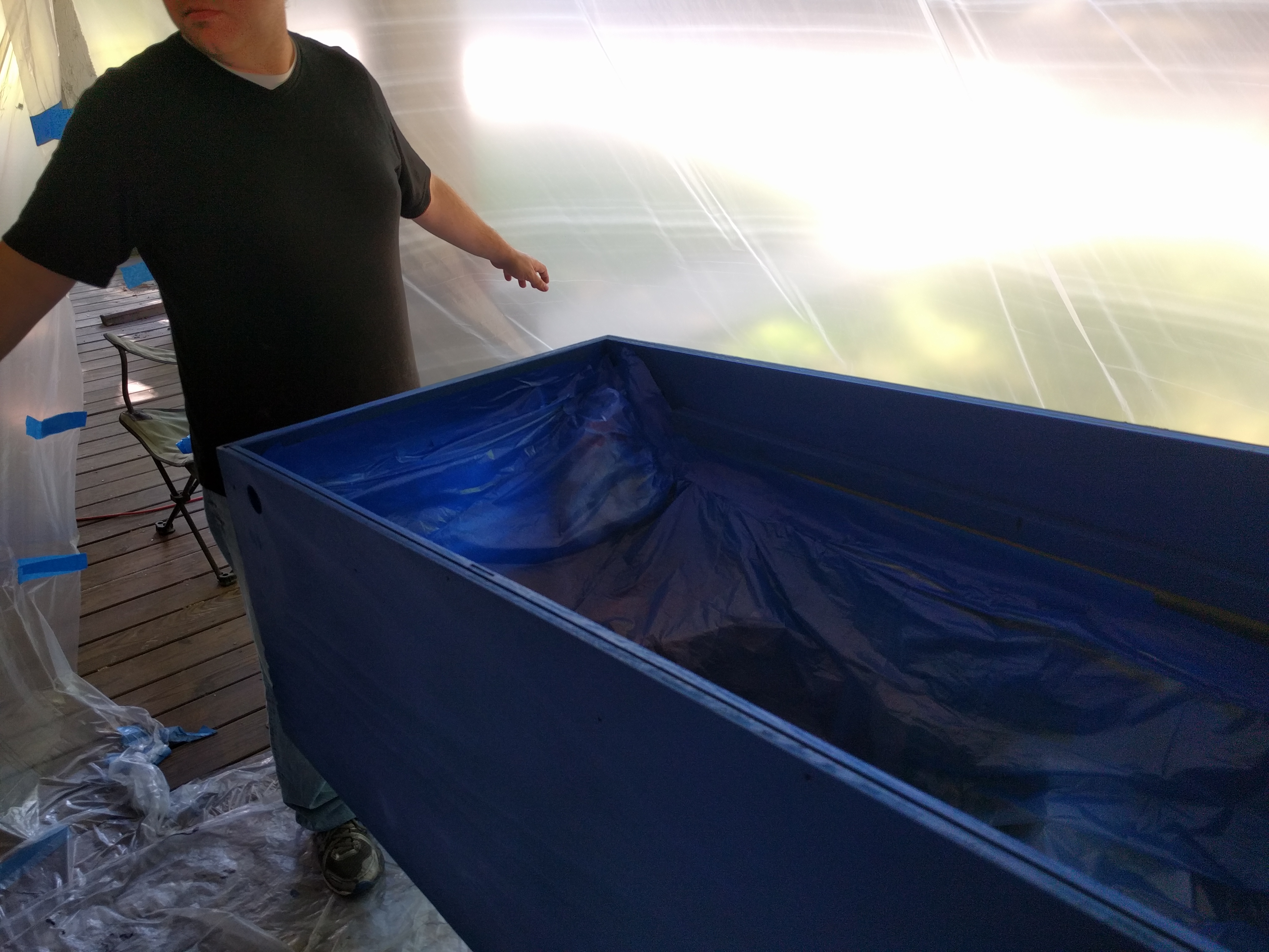
Figure 27. The cabinet after the application of the first coat of blue paint. |
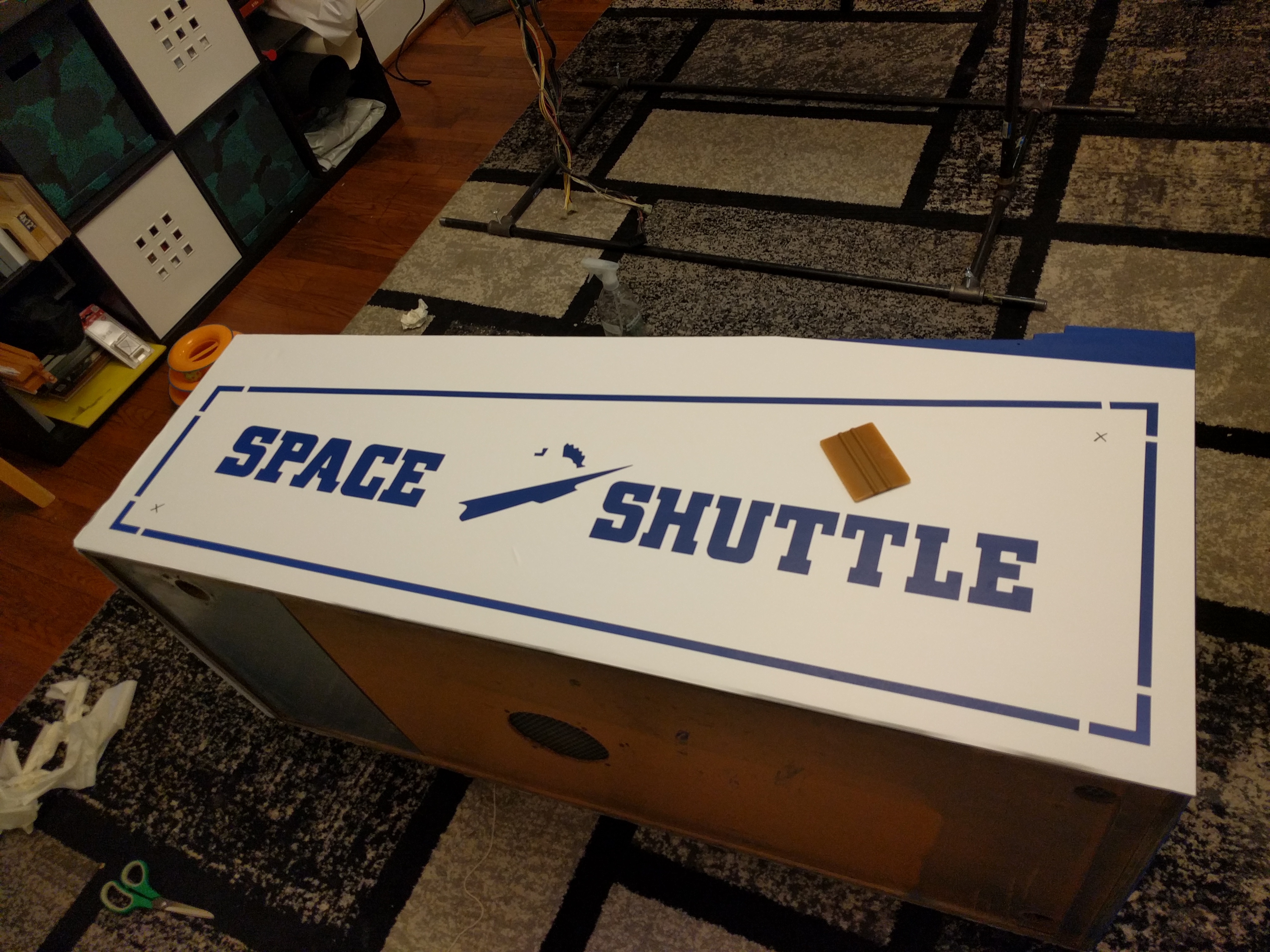
Figure 28. After the blue coats, stencils were applied to each side for the red coats. |
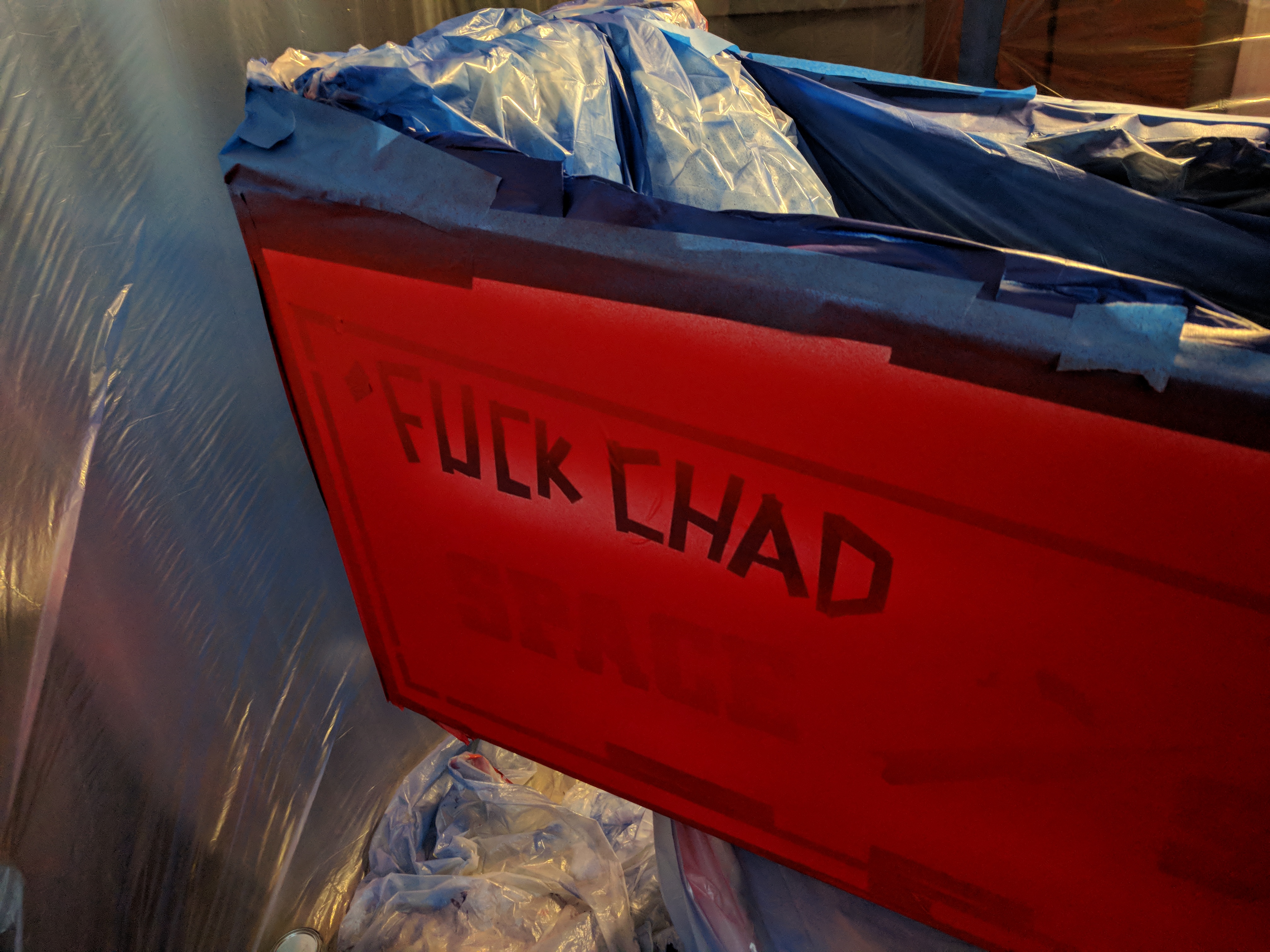
Figure 29. After the first application of the red coat. During stencil application, one engineer chose to write invective towards another engineer in tape. However, the target engineer reported not a feeling of offense but instead a feeling of amusement. This suggests that the original engineer's goal may not have been accomplished successfully. |
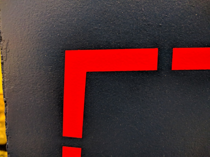
Figure 30. When applied correctly, the stencils were very effective at making sharp color edges. |

Figure 31. After the red coats were complete, the stencils for the white coats were then applied. Note the lack of invective; this is likely correlated with the potential failure of the previous invective attempt. |
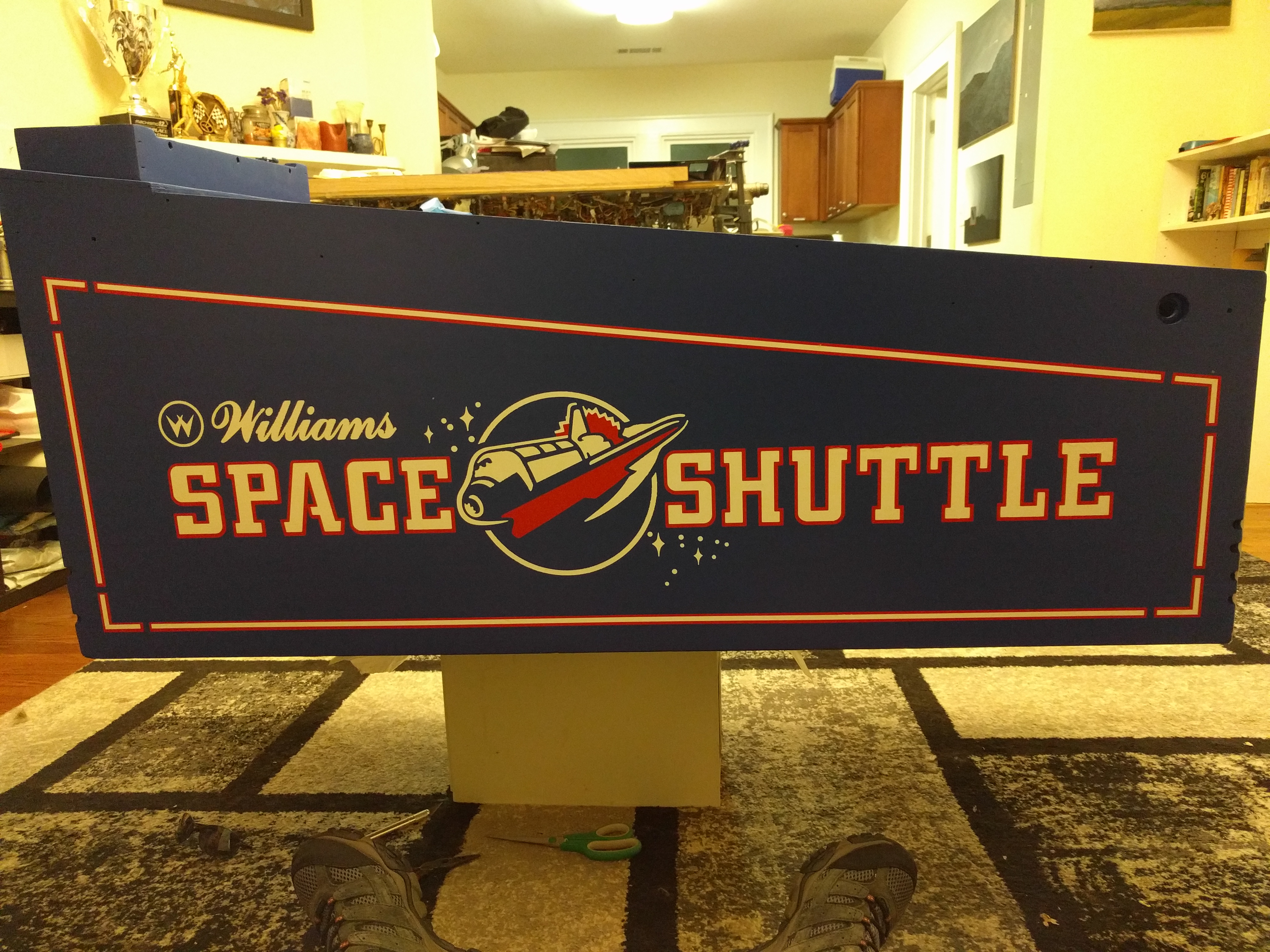
Figure 32. After painting was finished, it was decided that the stencils were highly effective and performed as desired. |
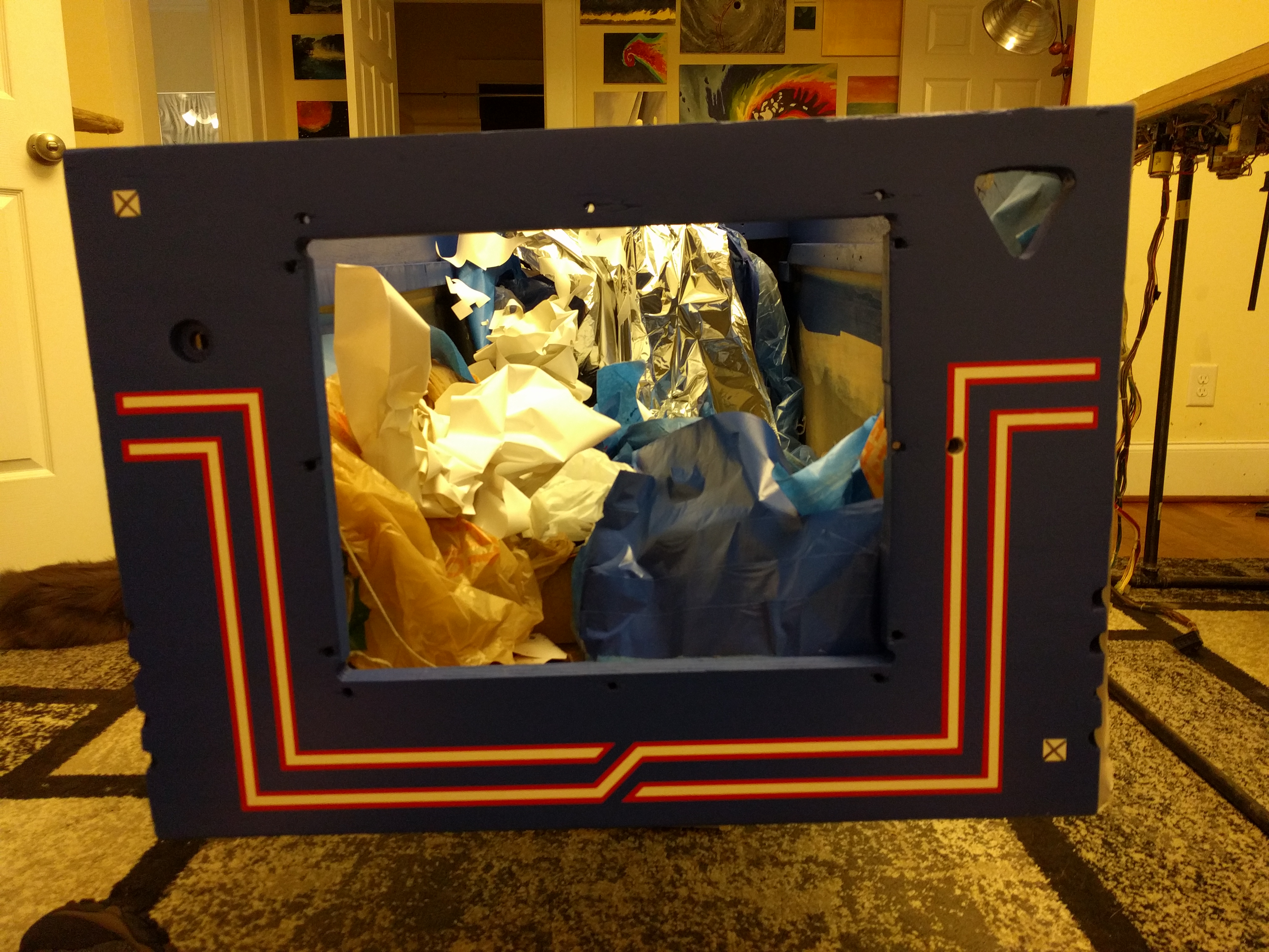
Figure 33. Another picture of the completed painting, from the front. |
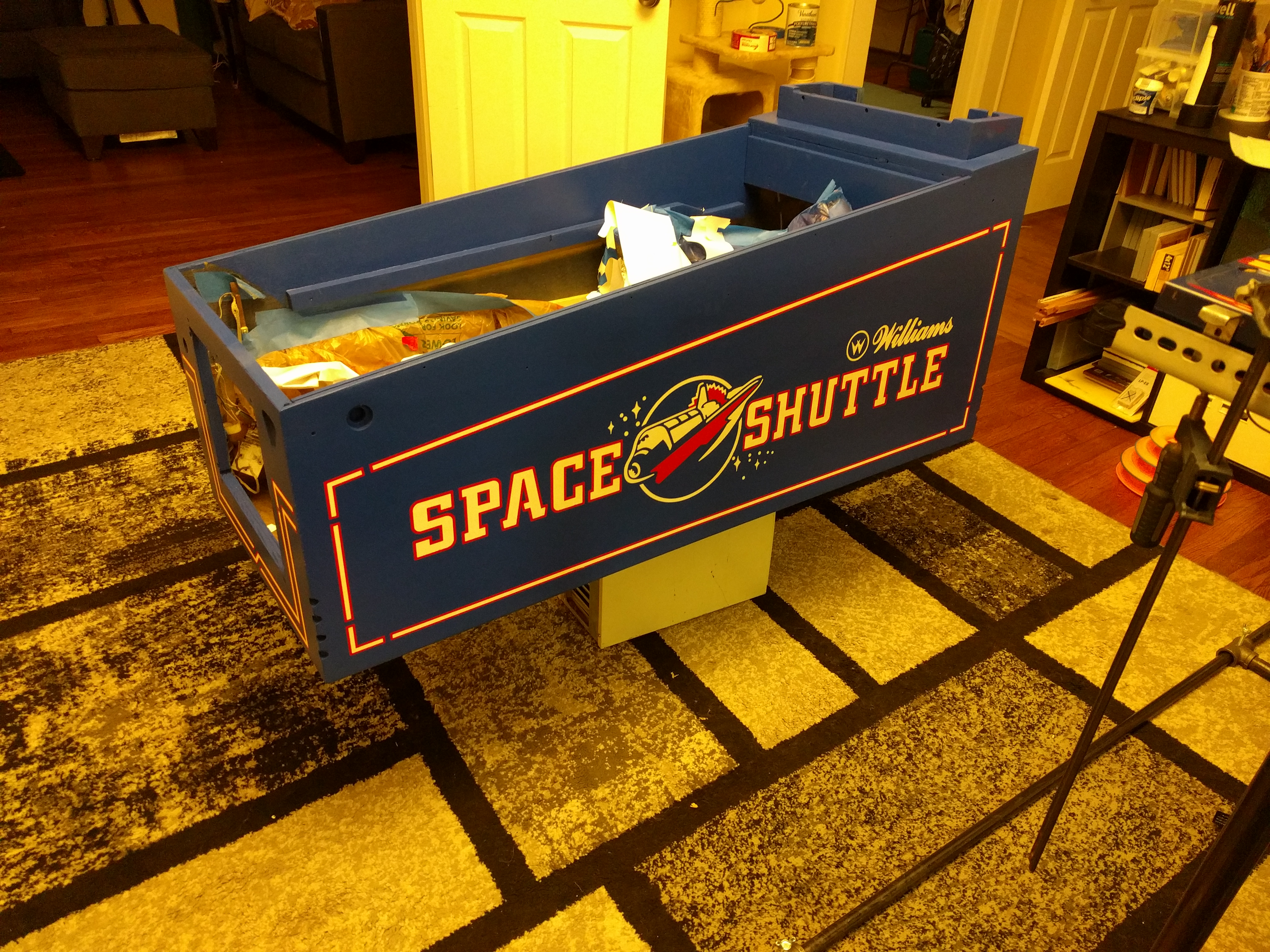
Figure 34. The completed cabinet from the right side. |

Figure 35. In many places, the detail came out very sharp. |
Figure 36. In other places, there were slight stencil issues. |

Figure 37. On the right side of the backbox, part of the stencil was incorrect and had to be completed by hand. It was decided that the engineer who did this (pictured) performed an adequate job. |
Overall, the cabinet restoration process was highly time-consuming and effort-intensive, but the results revealed a machine that was significantly more attractive than before. At this point in the project, it was postulated that it could, in fact, be possible to use the Space Shuttle for increased social standing.
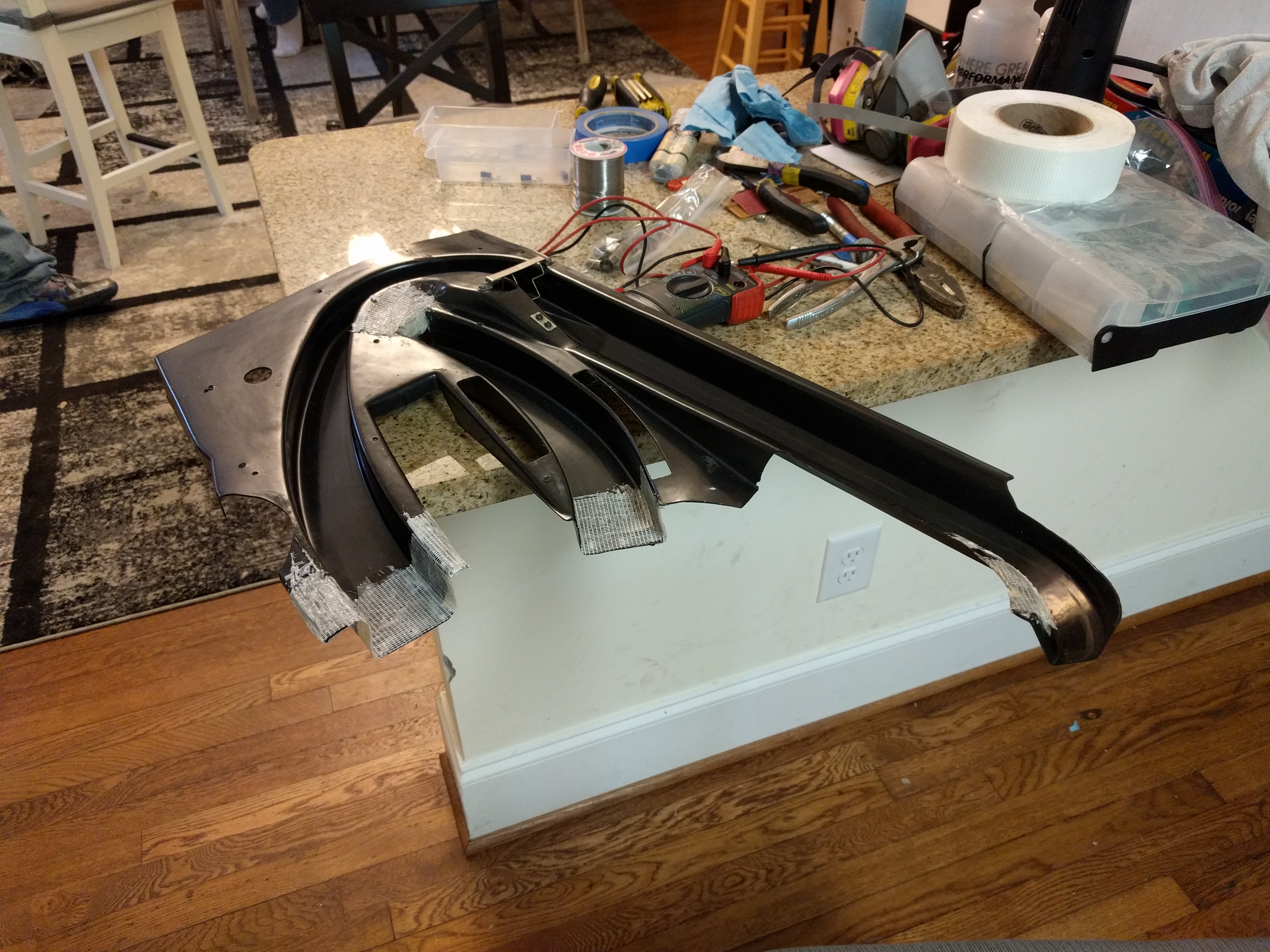
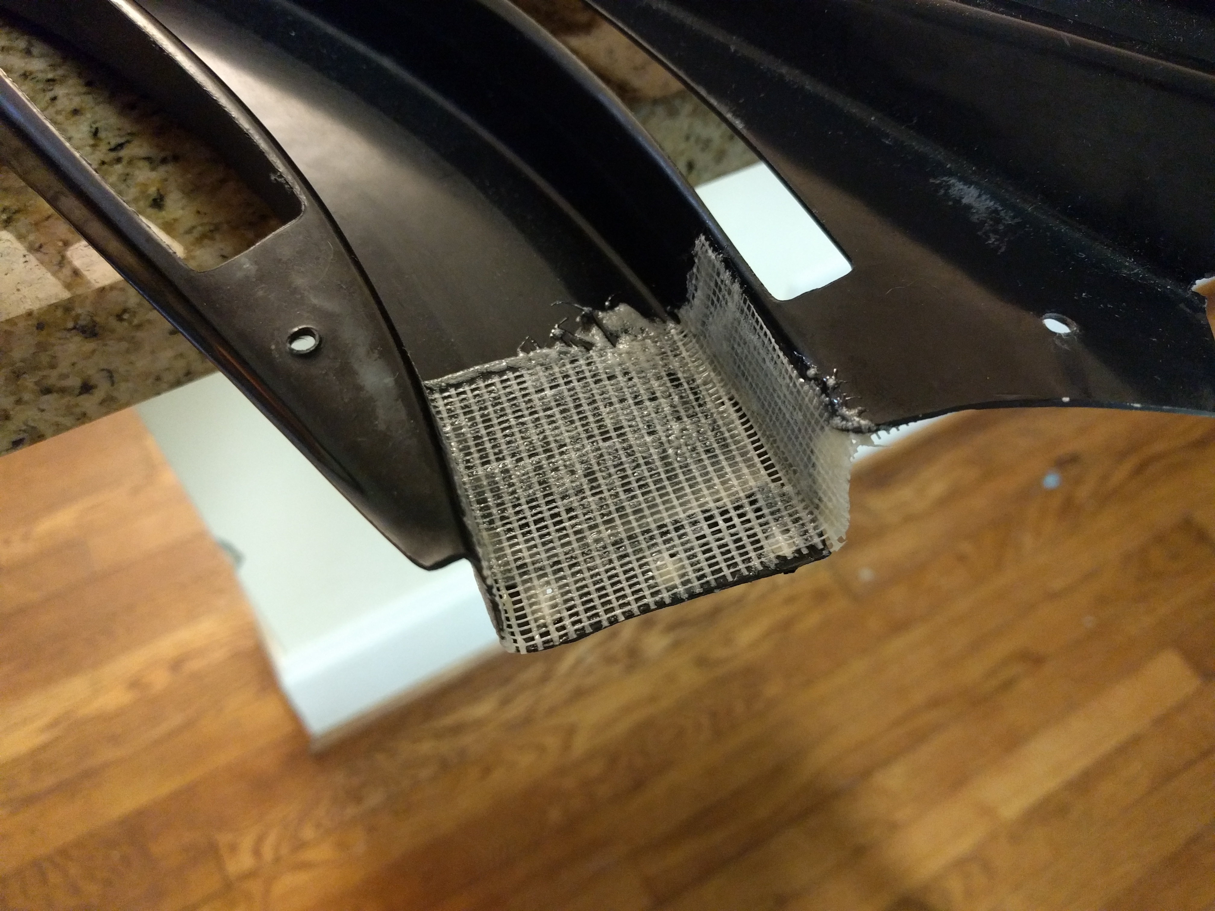
During the reassembly process, it was found that the plastic molding that made up the ramps on the playfield was in very poor condition and could not be re-affixed to the playfield. Therefore, fiberglass was used to rebuild those parts of the ramp that had been damaged, due to the high cost (and unavailability) of replacement ramp moldings. The directions of Ed Cheung were followed for this process [16]. Figures 38 through 40 show this process.
Although some minor repair details have been omitted from this process, at this point the engineers involved in the project could find no other reasons to delay the reassembly of the machine. Therefore, they finished reinstalling everything. Before this could be completed, the feline residents had to be removed from the cabinet. See Figure 41.
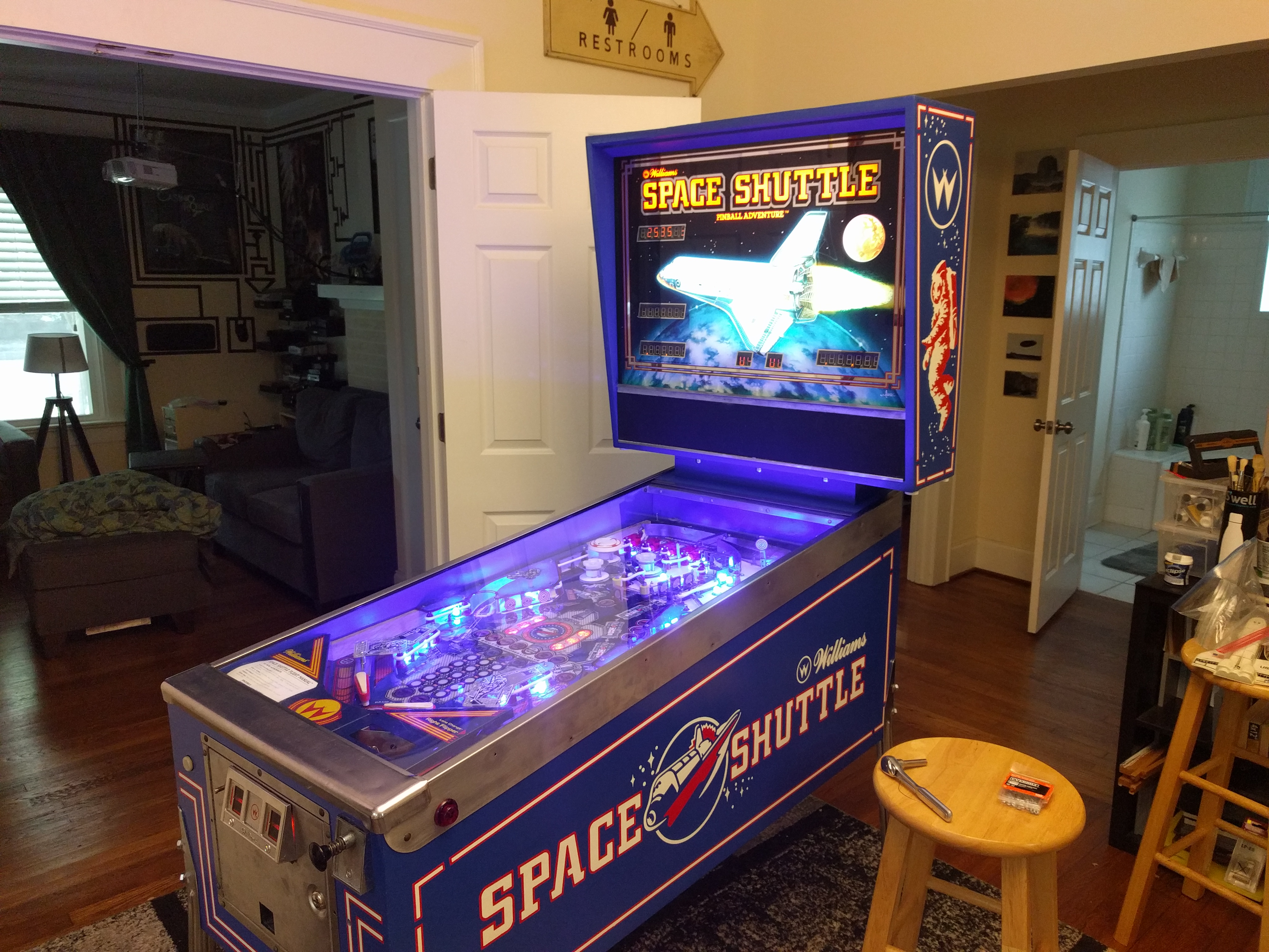
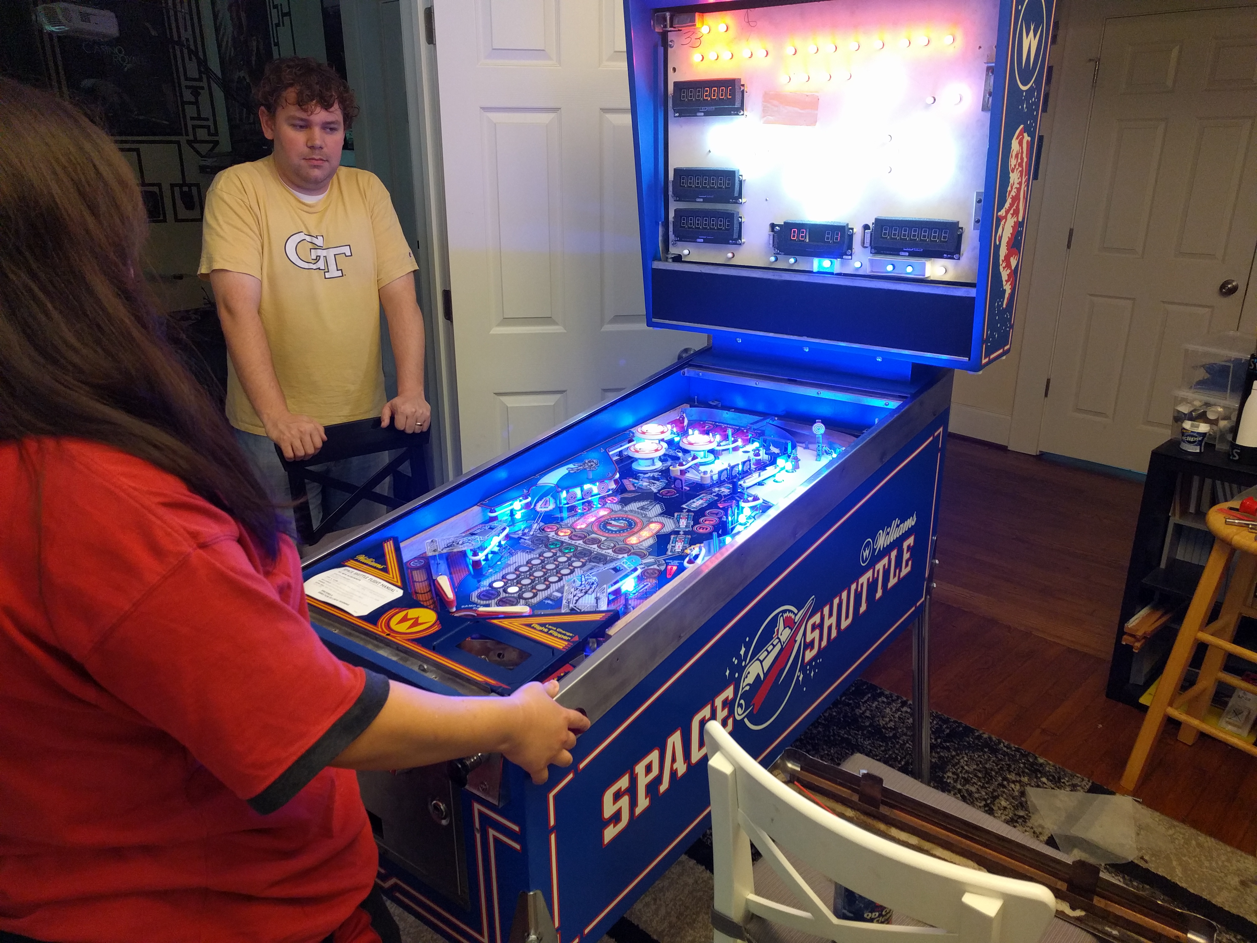
Figures 42, 43, and 44 show the final steps of reassembly and the finished machine. Figure 45 even demonstrates the machine in use (though the backglass is removed).

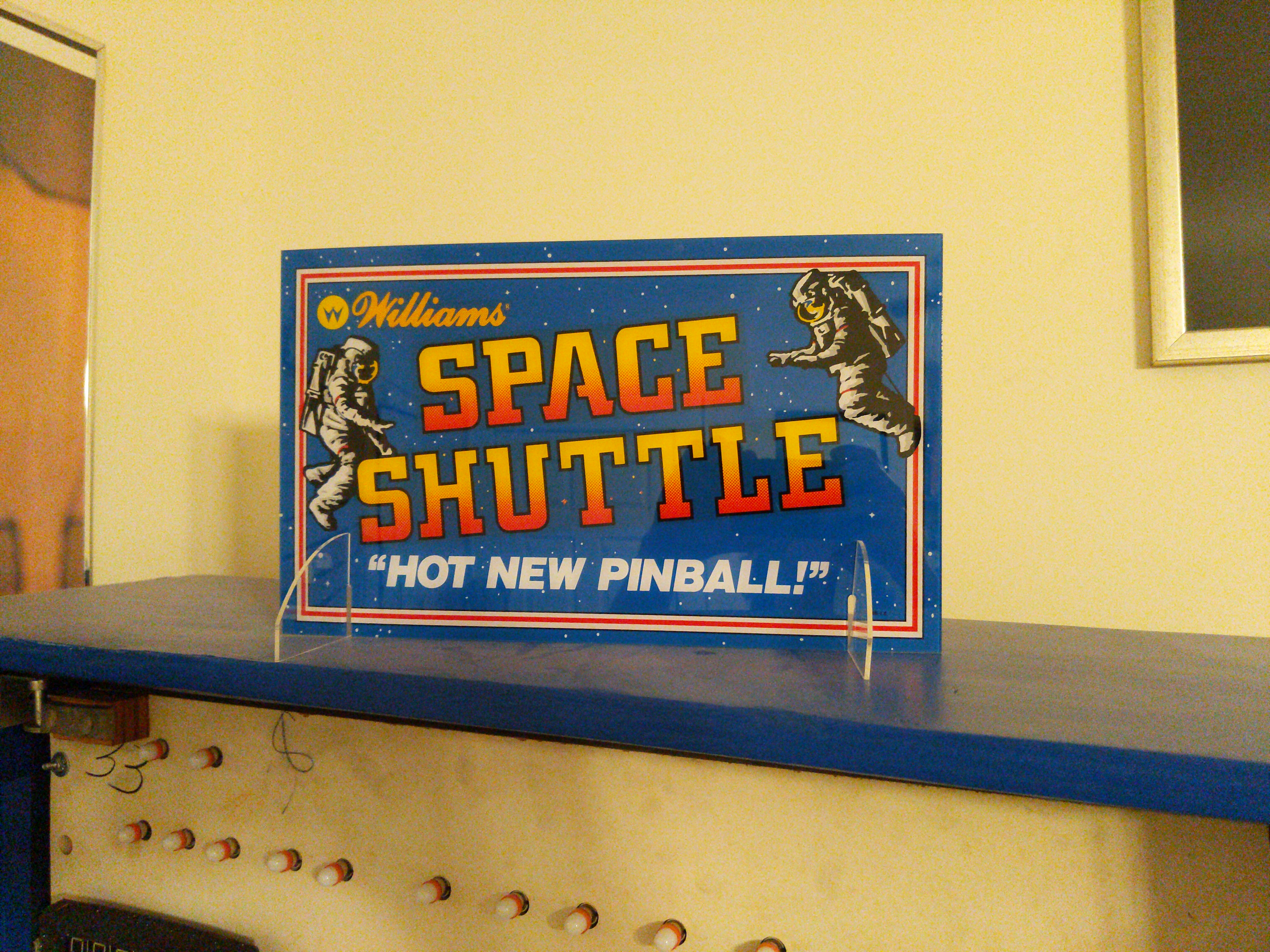
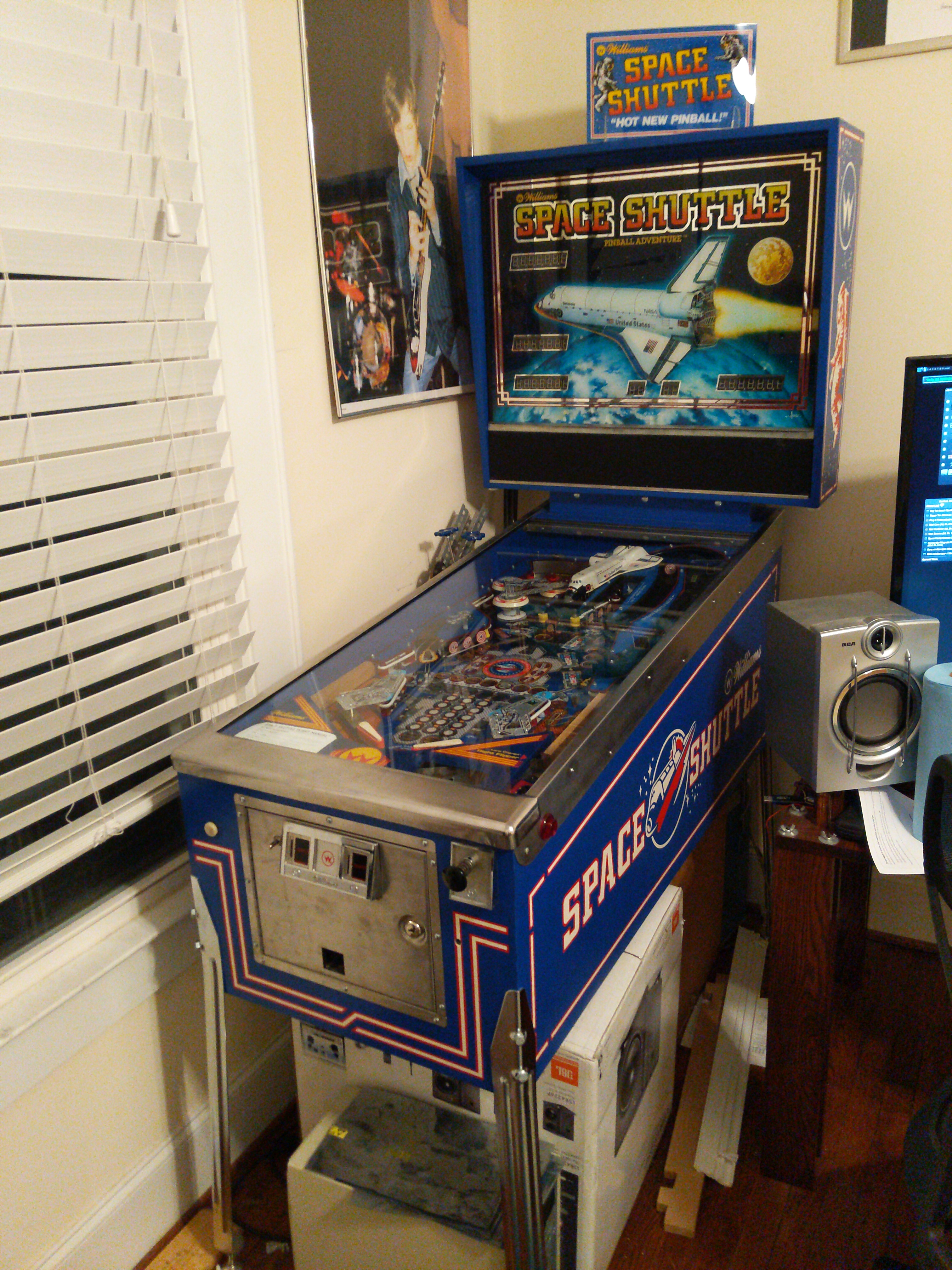
In the pinball community, evidence and interactions indicate that enthusiasts take `toppers' very seriously. Thus, a topper was fabricated. See Figure 46.
After reassembly, the Space Shuttle was installed in an easily accessible and playable position, shown in Figure 47. However, visitors to the house that contained the Space Shuttle only rarely even entered the room with the pinball machine, and even rarer was a request to play it. On those few occasions when the Space Shuttle was played, the machine performed successfully, but in each case post-play observations did not indicate increased social standing on the part of the engineers involved in the project. In fact, a low point in the experimentation came when the niece of one of the engineers, approximately eight years old, reported that the pinball machine was ``boring''. It is currently not known how to advertise pinball to grade school girls, and this is not currently an avenue of future exploration.
While the engineers involved in this project did---at needless expense---restore every part of the Space Shuttle, a functional and working pinball machine did not result in the originally-anticipated social gains. In fact, even expertise at the game did not seem to have much effect other than discouraging others to play, lest they be resoundingly beaten in a multiplayer game.
However, there were positive observations. In a solo setting, the machine was found to be reasonably fun to play and a nice distraction from the endless tedium of emails that makes up so much of the modern working world. It was also found to be enjoyable to attempt to imitate the TI speech chip's output, even when not playing or even in the vicinity of the machine.
In the end, the experiments were declared a mixed success and the machine was put up for sale [17], where it sold relatively quickly. (The original MPU board was replaced before sale.) The purchasers of the machine, a man and his daughter, expressed significant excitement about the machine. This led to the speculation that the experiments had been performed in the incorrect social circle, and that in a different social circle the intended outcome could have been achieved. It is an open question whether replacement of the engineers' entire social circle with pinball enthusiasts would have the intended result, or be desirable overall. No plans currently exist to investigate that hypothesis.
Instead, future work is focused on the hypothesis that a newer pinball machine or some different kind of arcade game might be both more enjoyable in a singleplayer and a multiplayer setting. It is also hypothesized that purchasing a machine in better condition could be a good idea.